


reef-pi :: An opensource reef tank controller based on Raspberry Pi.

And one last question for today.
I notice a lot of the breakout boards use 5v and Ground fro the GPIO on the pi, I know I can power the pi using 5v straight to the GPIO pins but which pin numbers am I best to connect the 5v to run the pi. I'm thinking along the lines of using an adapted PC power supply and making some sort common of 5v and ground rail and 12v and ground rail.
Do you think this would be ok? I figured pin 2 and 6? to power the pi?
Also is this pin out still relevant now that pi 2.0 beta 3 is out?
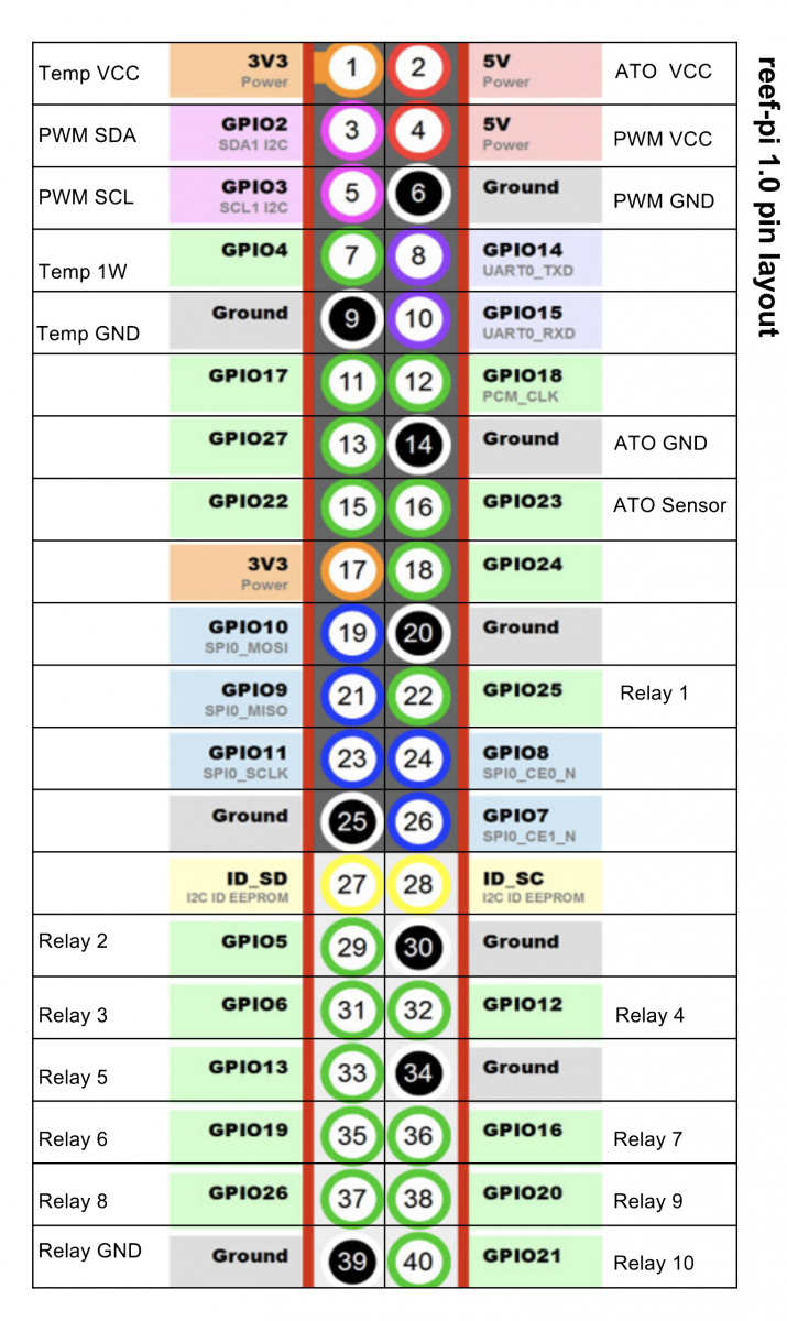
pinout-1.0.png
It is mostly relvant (some are not). If you are powering pi via GPIO (I always do), always use pin number 2 (serial number, not GPIO number)
details: https://www.modmypi.com/blog/how-do-i-power-my-raspberry-pi
Only my first generation build used things that are powered from Pi ,, all second and third generation builds (current ones) uses a single power rail for each individual voltages (5, 10, 12v) and common ground.

 
Is there an accurate doc on how to hook up a 18B20 temp sensor? I have the sensor, and understand the VCC, GND, and the 4.7k pullup, but what pin on the Pi do I attach the data line to so that the 2.0 beta Reef-Pi software can find it? I'm not finding any options in the menus to specify an IO pin for a temp sensor.

Docs on the Reef-Pi web site are out of date for the beta software release.
Always use GPIO 4 (serial number 7, label: temp 1w) to connect the temp sensor data line. This is not a choice, hence not available from UI. If you dont connect them to GPIO4 , they wont be detected and you wont see them in temperature probe drop down menu.
The website (official docs) are for 1.0, and they have many things that are different in 2.0 (which is in beta), but this is (temperature sensor) is same. We''ll have updated docs right before 2.0 final release goes out. We are at least couple of months away from that. Theres still a lot of UI polishing needs to be done, and at least two big features.
 
I am not sure it if matters but this is not exactly how i have mine... I have the Resister between the probe data and power ... Using that board with Connected rows is not forcing thru the resister but just adding it to the circuit.. ( I COULD BE WRONG )

They way mine is wired you would need to move the yellow data wire a row over . have resister go from red wire to that row then a jumper from there to the yellow data to sensors.. You have it so the data is bypassing the resister kinda like parallel not in line ...
What i mean is the probe data wire cant be on the same rail as the gpio data .. as the current can bypass the resister. Hope this does not sound stupid...

Again It may not matter but i think it does....

Do you have a picture of your wiring for this? Still trying to figure it out.
 
Ok so I'm getting 3.3v across the whole board, even on the data line. Does that seem right or what should I be getting
 
Ok so I'm getting 3.3v across the whole board, even on the data line. Does that seem right or what should I be getting
Are you getting 3.3V on the GND as well? Did you re-check that the pin on the Pi that you are connected to is a GND pin?
It doesn't matter which 3.3V or GND pin that you use.
Here are a few other pictures that may help.

DS18B20_pinout.jpg


DS18B20_schematic.jpg


DS18B20_wiring.jpg
 
Random thought I had. Anyone ever open up one of those wifi power strips. I wounder how lucky we could be that the outlets are hooked up to 5v relays, and you could replace the controller with a pi and create something with a simlar form factor to a Apex jr
41yBavxmD4L._AC_SY400_.jpg
 
Just added expand button to ph, ato, temperature probes and lights. With multiple probes/sensors the module specific tabs was getting longer, since each probe/sensor has configuration details, charts etc. Now all the details will be hidden, for individual probes/sensors, unless user click the 'expand' button.
Screen Shot 2018-06-26 at 8.00.43 AM.png
Screen Shot 2018-06-26 at 8.00.33 AM.png
Screen Shot 2018-06-26 at 8.00.21 AM.png


fixed the dashboard loading bug also, where users have to click on ph or temperature tab to get the relevant charts to appear in main dashboard: https://github.com/reef-pi/reef-pi/pull/422
 
Ok so I'm getting 3.3v across the whole board, even on the data line. Does that seem right or what should I be getting
Do you have one wire enabled? What happens when you do:
Code:
ls /sys/bus/w1/devices/

if you dont have the w1 directory, then one wire protocol is not enabled.
 
I have a VERY ODD issue..

Yesterday i decided to plug in all 4 temp sensors at the same time.. I have been using two.. and tested all of the stereo jacks with the two wired probes.. Last night ,well yesterday, When i plugged 4 temp probes into the jacks .. set them up.. they would drop to 32 deg then the sensors would disappear .. So .. i was racking my brain...

I then wired all 4 probes together and plugged them into one of the jacks and they all work fine... Same length of wire, Same configuration in the break out box connected to the main unit with serial db9 cable of 12 ft .... only difference is the 2 ft cable that came on the probes are now connected together then to 1 of the 4 outlets.. To add to this mystery . all of the 4 stereo Jacks pick up all 4 probes in this configuration.. ....

Any Thoughts... My guess issue with the Jacks themselves... they are cheap...
 
or just use the pi wifi
Never thought about this before...
if reef-pi Cound interface to wifi devices (I assume thru serial emulation) on board the RP .. It would open a huge door to available add on devices... Thou i am not convinced its a STABLE thing to try to implement ...

Just a thought
 
How do I wipe the database to start over? I have an equipment that I can't delete.

Screen Shot 2018-06-26 at 10.57.24 AM.png


Found it:
root@seahorse:~# systemctl stop reef-pi.service
root@seahorse:~# mv /var/lib/reef-pi/reef-pi.db ~
root@seahorse:~# systemctl start reef-pi.service
 
Last edited:
I have a VERY ODD issue..

Yesterday i decided to plug in all 4 temp sensors at the same time.. I have been using two.. and tested all of the stereo jacks with the two wired probes.. Last night ,well yesterday, When i plugged 4 temp probes into the jacks .. set them up.. they would drop to 32 deg then the sensors would disappear .. So .. i was racking my brain...

I then wired all 4 probes together and plugged them into one of the jacks and they all work fine... Same length of wire, Same configuration in the break out box connected to the main unit with serial db9 cable of 12 ft .... only difference is the 2 ft cable that came on the probes are now connected together then to 1 of the 4 outlets.. To add to this mystery . all of the 4 stereo Jacks pick up all 4 probes in this configuration.. ....

Any Thoughts... My guess issue with the Jacks themselves... they are cheap...
that is strange :-/ . Can be due to powerdraw as well.. ds18b20 has known limitations around length of the chord, i guess by reusing a single jack, you are limiting the overall wire length that the signal has to traverse.
 

ARE YOU READY TO CONFESS TO CRAZIEST, DUMBEST, FUNNIEST THING YOU’VE EVER DONE IN REEFING?

  • Yeah, I'll confess! (Share your story in the comments!)

    Votes: 17 56.7%
  • Nah, I'll keep mine a secret...(Don't be like that, share with the class!)

    Votes: 13 43.3%
Back
Top
Home
Post thread…
Market
What's new










