Another Open Source pH module

Michael Lane

Well-Known Member
View Badges
Joined
Aug 11, 2018
Messages
677
Reaction score
1,121
Rating - 0%
0   0   0
The ADM3260 has been in short supply lately, so it inspired me to try a new design for a pH module. It's also an excuse to learn how to use STM8 chips. I made a few mistakes with the layout, but here's a corrected schematic and layout.

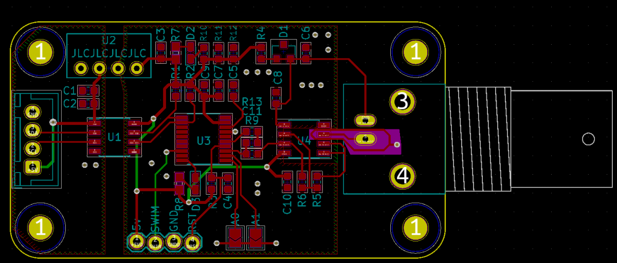
1577242718655.png


1577242767763.png


I'm still working on the firmware, but I've got a timer and LED flashes working. I hope to have the ADC working tomorrow, then it's on to I2C interface. I plan to make it compatible with RobertoB's design. I'll also have it up on GitHub pretty soon.

 

theatrus

Valuable Member
View Badges
Joined
Mar 26, 2016
Messages
2,253
Reaction score
3,603
Location
Sacramento, CA area
Rating - 0%
0   0   0
The ADM3260 has been in short supply lately, so it inspired me to try a new design for a pH module. It's also an excuse to learn how to use STM8 chips. I made a few mistakes with the layout, but here's a corrected schematic and layout.

1577242718655.png


1577242767763.png


I'm still working on the firmware, but I've got a timer and LED flashes working. I hope to have the ADC working tomorrow, then it's on to I2C interface. I plan to make it compatible with RobertoB's design. I'll also have it up on GitHub pretty soon.

Good concept; very similar to the Atlas Scientific probes which opt for the ADC interface on a small PIC8. STM8, EFM8 are all good options if the ADC isn't totally bad :)
 
OP
OP
Michael Lane

Michael Lane

Well-Known Member
View Badges
Joined
Aug 11, 2018
Messages
677
Reaction score
1,121
Rating - 0%
0   0   0
@theatrus Thanks for the feedback! I still feel like I have a lot to learn about analog circuits. I'll have to check out the EFM8 chips one day.

@LC8Sumi This is isolated. It uses RFM-0505S for power isolation and ISO1540 for I2C isolation.

Basically, this design biases the pH signal around 2.5v. The signal is fed into a buffer, then amplified before being read by the ADC in the STM8S. The power and signal are isolated.
1577280210710.png


I've added some annotations the schematic.
1577280538711.png
 

theatrus

Valuable Member
View Badges
Joined
Mar 26, 2016
Messages
2,253
Reaction score
3,603
Location
Sacramento, CA area
Rating - 0%
0   0   0
@theatrus Thanks for the feedback! I still feel like I have a lot to learn about analog circuits. I'll have to check out the EFM8 chips one day.

@LC8Sumi This is isolated. It uses RFM-0505S for power isolation and ISO1540 for I2C isolation.

Basically, this design biases the pH signal around 2.5v. The signal is fed into a buffer, then amplified before being read by the ADC in the STM8S. The power and signal are isolated.

1577280210710.png


I've added some annotations the schematic.
1577280538711.png
Ill post up my “jack scale” isolates adapter schematic in a few. Never built it in volume but it’s roughly the same topology / design, but using an ADM for size.
 

Ranjib

7500 Club Member
View Badges
Joined
Apr 16, 2016
Messages
9,876
Reaction score
16,682
Location
Pleasant Hill, Concord
Rating - 0%
0   0   0
This is awesome @Michael Lane .
Im curious what advantage the MCU provides over using raw ADC?
Unrelated question, how you derive the decoupling capacitor values? From datasheets or some other means
 

theatrus

Valuable Member
View Badges
Joined
Mar 26, 2016
Messages
2,253
Reaction score
3,603
Location
Sacramento, CA area
Rating - 0%
0   0   0
This is awesome @Michael Lane .
Im curious what advantage the MCU provides over using raw ADC?

More flexibility - if you don't like a protocol, address, or want to localize oversampling or add features (alarming, etc) you can do it in an MCU. Many chips on the market these days are actually MCUs, maybe with a mask rom to cut costs, since the designs are already done and its now a software problems. Downsides are of course now requiring extra programming and process steps.

Unrelated question, how you derive the decoupling capacitor values? From datasheets or some other means

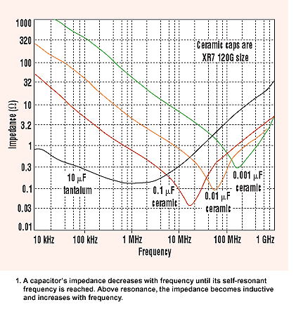
Step 1: Look at the datasheet
Step 2: If no data, use 0.1uF for digital and 1uF for analog for low/mid speed digital signals. If high speed, consult charts and add multiples (0.1uF, 0.01uF, etc)
O1WpV.png

Step 3: Test if you're able. RF / EMI testing is a good telltale. Or just assume all is well and carry on.
 
OP
OP
Michael Lane

Michael Lane

Well-Known Member
View Badges
Joined
Aug 11, 2018
Messages
677
Reaction score
1,121
Rating - 0%
0   0   0
This is awesome @Michael Lane .
Im curious what advantage the MCU provides over using raw ADC?
Unrelated question, how you derive the decoupling capacitor values? From datasheets or some other means
Theatrus nailed these answers. :)
I chose a MCU in order to add some processing to the signal. I'm oversampling and planning to add some rejection logic. I'm hoping this results in a more stable pH reading. I also wanted to learn a bit about another microcontroller since the programmer is so easily available.
 
OP
OP
Michael Lane

Michael Lane

Well-Known Member
View Badges
Joined
Aug 11, 2018
Messages
677
Reaction score
1,121
Rating - 0%
0   0   0
Here is roughly the circuit. Same analog components I use on the Pico boards. Processor differs there (SAMD10). Feel free to ignore or crib as much as you want :)

1577425045568.png

1577424978237.png

1577425215544.png


The isolation consumes a lot of space, but the rest is 0402 packages
Very cool! Thanks for sharing. I love seeing other designs, especially to see what I understand and what I can still learn.

0603 is probably as small as I'll go. They're already tiny enough to place as it is. I was considering one of the super cheap pick and place machines if the 25% tariff is ever dropped.

I haven't tried QFN components yet, but I've found that I don't like those little resistor networks. It's always a short or an open on those things whenever one of my boards fails testing.
 
OP
OP
Michael Lane

Michael Lane

Well-Known Member
View Badges
Joined
Aug 11, 2018
Messages
677
Reaction score
1,121
Rating - 0%
0   0   0
Very nice board. Would this design be able to be adapted for ORP as well? I seem to recall that when I looked at the Reef Angel schematics for their PH and ORP circuits, they were not too different from each other.

Dennis
The general design could probably be used for ORP, but R6 may need to be changed since ORP probes generate a different range of voltages. I may have to pick up an ORP probe to test it out.
 

Bigtrout

Valuable Member
View Badges
Joined
Dec 16, 2018
Messages
1,189
Reaction score
2,811
Rating - 0%
0   0   0
Very cool! Thanks for sharing. I love seeing other designs, especially to see what I understand and what I can still learn.

0603 is probably as small as I'll go. They're already tiny enough to place as it is. I was considering one of the super cheap pick and place machines if the 25% tariff is ever dropped.

I haven't tried QFN components yet, but I've found that I don't like those little resistor networks. It's always a short or an open on those things whenever one of my boards fails testing.
If you need a beta tester im a willing guinea pig. I could compare your new design vs the reef pi board in the same tank. I think this is worthy of me ordering a 2nd ph probe if you need the help.
 

Ranjib

7500 Club Member
View Badges
Joined
Apr 16, 2016
Messages
9,876
Reaction score
16,682
Location
Pleasant Hill, Concord
Rating - 0%
0   0   0
More flexibility - if you don't like a protocol, address, or want to localize oversampling or add features (alarming, etc) you can do it in an MCU. Many chips on the market these days are actually MCUs, maybe with a mask rom to cut costs, since the designs are already done and its now a software problems. Downsides are of course now requiring extra programming and process steps.


Step 1: Look at the datasheet
Step 2: If no data, use 0.1uF for digital and 1uF for analog for low/mid speed digital signals. If high speed, consult charts and add multiples (0.1uF, 0.01uF, etc)
O1WpV.png

Step 3: Test if you're able. RF / EMI testing is a good telltale. Or just assume all is well and carry on.
Thank you :-) super duper useful .
 
OP
OP
Michael Lane

Michael Lane

Well-Known Member
View Badges
Joined
Aug 11, 2018
Messages
677
Reaction score
1,121
Rating - 0%
0   0   0
I've made a bit of progress. The tiny blue wire in the middle fixes a routing mistake.

I've got the ADC working, but I've hit a bit of blocker with I2C. If timer interrupts are enabled, the I2C bus gets corrupted after a variable amount of time; it doesn't hang if I don't enable the timer...

It always seems to be after transmitting a reading (2 bytes) and then getting a slave address match again. For some reason it isn't letting go of the clock... This is the first time I've worked on creating a I2C slave device, so I guess it should be expected.

I think it will be ready for the first test once I get that figured out. I'll assemble a couple more if it runs smoothly for a few days.

IMG_20191227_132838.jpg
 

Ranjib

7500 Club Member
View Badges
Joined
Apr 16, 2016
Messages
9,876
Reaction score
16,682
Location
Pleasant Hill, Concord
Rating - 0%
0   0   0
I think I finally got it! I've had it running for a couple hours now, and it's still going well. I'll get this on a reef-pi and see how it does over the weekend.
1577488081733.png
Sweet :-) , Keep us posted, im getting excited about this. Are you emulating the i2c protocol same as the existing ph board, or we'll need a new driver.
 
OP
OP
Michael Lane

Michael Lane

Well-Known Member
View Badges
Joined
Aug 11, 2018
Messages
677
Reaction score
1,121
Rating - 0%
0   0   0
This board doesn't support everything that RobertoB's board supports, but it is compatible with the existing driver. That was one of my design goals.

I've still got a bit of clean up work to do on the firmware, but I think it's 100% functional now! I ended up going back to the data sheet to inspect each register when the board was locking up. It looks like the ST library I was using didn't catch all of the events correctly. I think I'll also add a watch dog reset just in case something else goes wrong.
 
OP
OP
Michael Lane

Michael Lane

Well-Known Member
View Badges
Joined
Aug 11, 2018
Messages
677
Reaction score
1,121
Rating - 0%
0   0   0
I'm almost there with this, but I keep hitting snags with I2C. It seems that rpi doesn't support clock stretching, and occasionally the STM8S can't seem to keep up at 100 KHz. Plus it seems like rpi isn't rejecting the reading after a NAK.

I change the I2C clock speed to 50 KHz and I'm seeing much better results.
1577588572501.png
 

TOP 10 Trending Threads

DO YOU THINK TECHNOLOGICAL ADVANCEMENTS ARE MORE HELPFUL OR HURTFUL TO REEFING?

  • More helpful.

    Votes: 47 41.6%
  • More hurtful.

    Votes: 5 4.4%
  • I think it depends mostly on the technology.

    Votes: 45 39.8%
  • I think it dependsmostly on the reefer behind the technology.

    Votes: 34 30.1%
Back
Top
Home
Post thread…
Market
What's new