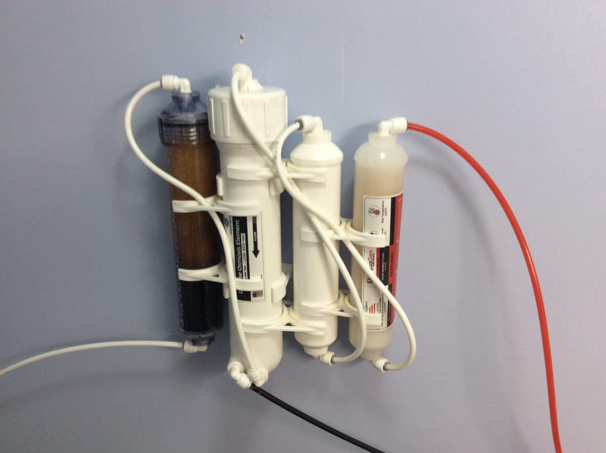

Can someone tell me how to hookup this float switch on RO filter

  • Thread starter Thread starter stanleo
  • Start date Start date
  • Tagged users Tagged users None

stanleo

Valuable Member
View Badges
Joined
Jan 11, 2014
Messages
1,534
Reaction score
1,931
Location
Statesville, NC
What state or country do you live in
North Carolina
Rating - 0%
0   0   0
My husband ordered this float valve and auto shut off for an RO filter and it didn’t come with instructions and I can’t figure it out. I’m hoping someone can tell me how to do it or send a link to a good YouTube video or instructions on how to hook it up.
08E18F86-1DB4-4332-BFCC-4CB2BFECDE19.jpeg
E54A835D-EFCF-4F26-8686-22200AED2547.jpeg
 
Looking at your kit, the blue-handled unit is a shut-off valve, and possibly the elbow with the red end could be a check valve. If you look at the written instructions link above you'll see some units use an elbow instead of a tube for the check-valve.
Look inside it/compare it to the other elbow. If there's no check-valve inside it, you'll need to get one or that ASO (auto shut-off) valve won't work.


Looking at your RODI unit, the red incoming water goes to your pre-filter (sediment label on canister), through your carbon, then the Membrane, and lastly your DI canister.
 
Image removed as it wasn't appropriate to the OP's setup.
Better image in post #11
 
Last edited:
Please correct if wrong.

Your source water to the unit is the red line correct? This should be attached to your homes plumbing.

The black line is the waste water drain line? This should go to a sink drain or outside.

The white line is the produced RO/DI water you use for the aquarium.
 
Ignore the 5th stage as you don't have it, and ignore the Faucet in the drawing.
The Drain Water is your Product Water coming out the bottom of your far left canister. Replace this (if you like) with the new Blue tubing. This way, Red is tapwater, Black is wastewater, and Blue is clean water.
 
Please correct if wrong.

Your source water to the unit is the red line correct? This should be attached to your homes plumbing.

The black line is the waste water drain line? This should go to a sink drain or outside.

The white line is the produced RO/DI water you use for the aquarium.
That's what I see ...
 
So the red line needs to be cut and put into the auto shut off valve.

The white product water line should be cut and put into the auto shut off valve.

The float valve should be installed in your storage container and connected to the free end of the produced water (White Line)
 
Here's a much better image. Only thing in it you Do Not have is item #4, and items #5 on your unit are hose instead of nipples.
If you can, print the picture and stare at your unit for a bit

1583805302955.png
 
Yes much better diagram.
The auto shut off valve can be installed in several spots and it will function.

Keep in mind the direction of flow
#1 is the source. In your case the red line
#14 is the output or produced RO/DI water. In your case the white line.
#12 is the waste water. In your case the black line.
 
So the red line needs to be cut and put into the auto shut off valve.

The white product water line should be cut and put into the auto shut off valve.

The float valve should be installed in your storage container and connected to the free end of the produced water (White Line)
To not confuse stanleo, all your current tubing going into this new ASO are WHITE in your picture
 
In this picture, the screws are out of sight facing down. Note the ASO is labelled IN and OUT
Your filtered water from stage 3 comes from your carbon (middle in your pic, white canister)
Filtered water to membrane goes to the single inlet on your housing with the screw-top.

Filtered water from membrane comes from the white tubing on the bottom of your housing (beside the black hose)
Filtered water to stage 5 goes to the top of your DI housing (far left in your image with the brown stuff inside)

1583806034800.png
 
Yes that's true in this diagram pictured.

Mind the flow though and read the in and out on the auto shut off valve.

My preference is for the valve to shut off the source to the entire unit
 
@Greg P you got this I am stepping out so I don't confuse further.
 
Look at my post #11 for item #8. This is where you need to install that new check valve from your kit (if it has a ball inside)
 
Yes that's true in this diagram pictured.
Mind the flow though and read the in and out on the auto shut off valve.

My preference is for the valve to shut off the source to the entire unit
@Greg P you got this I am stepping out so I don't confuse further.
I see what you're getting at. I'd like to have the OP use the images to get the unit working correctly first. Tubing is cheap and the unit can be re-plumbed later. Plus, they have a new source water valve, but they must have one already to shut it off.

Thanks for your help!!
 
I see what you're getting at. I'd like to have the OP use the images to get the unit working correctly first. Tubing is cheap and the unit can be re-plumbed later. Plus, they have a new source water valve, but they must have one already to shut it off.

Thanks for your help!!

You did a better job at the diagrams and explaining things, so the thanks is yours.
 
Just make sure the ASO works well and doesn’t significantly drop the pressure to your membrane. My ASO was doing that, and when I took it out of the system, it became way quicker and more efficient.
 

TOP 10 Trending Threads

WHAT DO YOU ALWAYS RUN OUT OF AT THE WORST TIME?

  • Salt mix

    Votes: 17 18.9%
  • Fish or coral food

    Votes: 5 5.6%
  • Test kits or reagents

    Votes: 9 10.0%
  • Filter media or replacement fleece

    Votes: 5 5.6%
  • RO/DI filters or supplies

    Votes: 14 15.6%
  • Fragging and repair supplies, like glue or epoxy

    Votes: 10 11.1%
  • I keep a backup of everything

    Votes: 23 25.6%
  • Other (Post in the comments)

    Votes: 7 7.8%
Back
Top
Home
Post thread…
Market
What's new