Chiller Electrical Help

goody

Well-Known Member
View Badges
Joined
Jan 2, 2010
Messages
993
Reaction score
188
Location
Carlsbad, CA
Rating - 0%
0   0   0
Last 2 days have felt like summer, so I thought I would get my chiller down from storage and put it inline on my macroalgae tank which hit water temp in mid 80s in the garage. It's a Current 1/15th chiller that I bought used several years ago and only used it for about a month which was quite awhile ago.
Plugged it in and I'm not getting any power. I'm not good with electrical issues, but I took the top off to look at the insides and things look good to someone that doesn't know what I'm looking at. Even though I bought it used, it was barely used and worked great when I texted it.
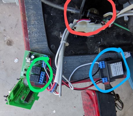
Any ideas on what it could be? Why I'm not getting any power? I've tried multiple outlets. By the way, I did get a jolt twice when I forgot to unplug it during a test and I touched the silver cylinder piece with the 2 white wires and also touched the wires on back of the power switch. I believe these are discontinued and I can't find any information on them. Maybe some of the wires are not in the correct slot? A few broke off and I reinserted them.

PXL_20250510_184634180.jpg PXL_20250510_184626929.jpg PXL_20250511_003100678.jpg PXL_20250510_191736959.jpg PXL_20250511_003155158.jpg
 

Pridedcloth3

Active Member
View Badges
Joined
Jan 9, 2022
Messages
356
Reaction score
276
Location
United States
Rating - 0%
0   0   0
If you have a volt meter you can check resistance in the capacitor. But if you're not familiar with electronics you probably shouldn't have opened it up. Without knowing what wire goes to what makes it about impossible for someone to diagnose 8,000 miles away. Hate to say it but you may have opened a can of worms.
 

W31Olds

Valuable Member
View Badges
Joined
Dec 13, 2024
Messages
1,784
Reaction score
1,529
Location
Timonium
Rating - 0%
0   0   0
That silver thing is a capacitor that can hold a charge and is usually used to supply startup current for the compressor. The little black box to the right in the 3rd slide looks to be a 9v transformer to run the power supply on the left of the same slide. If there is a fuse in the back of the unit you could check that but chances are it may be ok and your power supply circuit is bad and that's why the display fails to come on.
 

W31Olds

Valuable Member
View Badges
Joined
Dec 13, 2024
Messages
1,784
Reaction score
1,529
Location
Timonium
Rating - 0%
0   0   0
I assume when he states the power will not come on he means there is no front display indicators. If the compressor doesn't run it could be a capacitor but the display would still come on.
 
OP
OP
G

goody

Well-Known Member
View Badges
Joined
Jan 2, 2010
Messages
993
Reaction score
188
Location
Carlsbad, CA
Rating - 0%
0   0   0
That silver thing is a capacitor that can hold a charge and is usually used to supply startup current for the compressor. The little black box to the right in the 3rd slide looks to be a 9v transformer to run the power supply on the left of the same slide. If there is a fuse in the back of the unit you could check that but chances are it may be ok and your power supply circuit is bad and that's why the display fails to come on.
Thanks for the reply. There is no visible fuse and I don't see anywhere it could be. Are the 9v transformers on the circuit board that I circled in green? When you say power supply can possibly be bad, are you referring to the power switch in red or the black box in blue or those black boxes on the circuit board?
 

Attachments

  • PXL_20250511_003155158~2.jpg
    PXL_20250511_003155158~2.jpg
    220.3 KB · Views: 64
OP
OP
G

goody

Well-Known Member
View Badges
Joined
Jan 2, 2010
Messages
993
Reaction score
188
Location
Carlsbad, CA
Rating - 0%
0   0   0
If you have a volt meter you can check resistance in the capacitor. But if you're not familiar with electronics you probably shouldn't have opened it up. Without knowing what wire goes to what makes it about impossible for someone to diagnose 8,000 miles away. Hate to say it but you may have opened a can of worms.
Yeah, totally understand. I wasn't expecting wires to be broken off at the solder and not have any tell tale signs of where they're supposed to go. Unfortunately, I can't find the wiring schematic, but was able to find the manual, but that only had operation and maintenance information.
 

Pridedcloth3

Active Member
View Badges
Joined
Jan 9, 2022
Messages
356
Reaction score
276
Location
United States
Rating - 0%
0   0   0
Yeah, totally understand. I wasn't expecting wires to be broken off at the solder and not have any tell tale signs of where they're supposed to go. Unfortunately, I can't find the wiring schematic, but was able to find the manual, but that only had operation and maintenance information.
All i see is a wire that came out. All you would need is a small flat screw driver and you can get wire strippers or just use a lighter to expose nate wire. Back the terminal of 4 half turns reinsert the wire and tighten the terminal back down. If that's all there is is straight forward.
 

Pridedcloth3

Active Member
View Badges
Joined
Jan 9, 2022
Messages
356
Reaction score
276
Location
United States
Rating - 0%
0   0   0
I assume when he states the power will not come on he means there is no front display indicators. If the compressor doesn't run it could be a capacitor but the display would still come on.
I see, in that case I would agree. I'm under the impression it's not coming on at all.
 

jsmkmavity

Valuable Member
View Badges
Joined
Apr 21, 2023
Messages
2,477
Reaction score
3,909
Location
Sandpoint
Rating - 0%
0   0   0
The green circle is around what looks like relays. They probably supply power to the compressor and fan. The blue circle is around what looks like a transformer. That probably powers the display and control voltage for relays and maybe temperature control circuit.
We need to follow the path from the plug in power cord and see if you are losing it thru a switch, circuit board, or a safety (like low or high pressure switch on the refrigerant tubing or high tepmerature limit switch on the water tubing.
 

jsmkmavity

Valuable Member
View Badges
Joined
Apr 21, 2023
Messages
2,477
Reaction score
3,909
Location
Sandpoint
Rating - 0%
0   0   0
Please give us more details about what is or is not lighting up or coming on.
 

W31Olds

Valuable Member
View Badges
Joined
Dec 13, 2024
Messages
1,784
Reaction score
1,529
Location
Timonium
Rating - 0%
0   0   0
The 9v ac transformer is on the right circled in blue. You could measure the AC voltage output of the transformer at the blue 2 wire screw terminal and should read around 9 VAC. You can just put your meter probes right on the screws to measure. The little black boxes circled in green are relays along with the power supply on that circuit board. Unlikely, the 9v transformer on the right is the problem. If I had to guess the 9 volt transformer supplies 9 volt AC to the power supply board on the left which converts the 9 volt AC into a dc voltage (Likely 5 VDC based on the age of the unit) to run the microcontroller chip and display on the bottom circuit card. No offense but, without a strong electronics background and a schematic your in over your head. There may be resources and people that repair or sell refurbished circuit cards on the internet but if the compressor is bad the unit is junk.
 
OP
OP
G

goody

Well-Known Member
View Badges
Joined
Jan 2, 2010
Messages
993
Reaction score
188
Location
Carlsbad, CA
Rating - 0%
0   0   0
Appreciate all your time and effort in trying to help me out. The unit does absolutely nothing when plugged in. No lights on display or power switch,no compressor or fan kicking on...nothing. With it being Mother's Day, I probably can't get to it today, but I will see if there is an electrical on my local site to help or try and work through it with a voltmeter myself.

Wires that were not connected were the highlighted yellow on the circuit board. I pulled out the display so I could strip and reinsert. Didn't work. But when I gave up, I noticed the other end of those wires also disconnected at the other end on what is being called the transformer. I stripped those and reinserted but with the same results... absolutely nothing.
 

Attachments

  • PXL_20250511_003155158~3.jpg
    PXL_20250511_003155158~3.jpg
    217.2 KB · Views: 31

BeanAnimal

7500 Club Member
View Badges
Joined
Jul 16, 2009
Messages
9,274
Reaction score
15,564
Rating - 0%
0   0   0
I am afraid that you may be competing for a Darwin Award here. You have absolutely no idea what you are doing and are going to end up getting hurt or hurting somebody else. That capacitor could have easily killed you. Stripping wires and connecting them various places is not safe, nor is poking around with a meter if you have no idea what you are doing.

These are simple devices, but not typically user serviceable unless you understand how they work and/or have (or can sketch out) the schematic.

Please, just walk away and enjoy Mother’s Day. This is not a DIY project.
 

W31Olds

Valuable Member
View Badges
Joined
Dec 13, 2024
Messages
1,784
Reaction score
1,529
Location
Timonium
Rating - 0%
0   0   0
That brand appears to be quite old and considering that it is a small unit, it's probably not worth fixing. You would have to find someone that could fix the board if that was the problem which in itself is a problem because most Technicians just don't solder/replace components on boards anymore.
 
OP
OP
G

goody

Well-Known Member
View Badges
Joined
Jan 2, 2010
Messages
993
Reaction score
188
Location
Carlsbad, CA
Rating - 0%
0   0   0
I am afraid that you may be competing for a Darwin Award here. You have absolutely no idea what you are doing and are going to end up getting hurt or hurting somebody else. That capacitor could have easily killed you. Stripping wires and connecting them various places is not safe, nor is poking around with a meter if you have no idea what you are doing.

These are simple devices, but not typically user serviceable unless you understand how they work and/or have (or can sketch out) the schematic.

Please, just walk away and enjoy Mother’s Day. This is not a DIY project.
Appreciate your concern and you're right! I just thought because I have done things electrical in the house (Changing out ceiling fans, retrofitting can lighting, replacing light switches/outlet) I might be able to see an "easy" fix like a disconnected/broken wire or find that it was totally corroded inside and be done with it. As mentioned, going to see if there is an electrician on my local forum that can help otherwise will not attempt to repair.
 

IceNein

Well-Known Member
View Badges
Joined
Sep 1, 2017
Messages
907
Reaction score
1,491
Rating - 0%
0   0   0
I've seen plenty of them go bad. Highly doubt is disingenuous. I do repair in a refinery and they don't like temperature swings.

Having worked electronics in the Navy, capacitors, especially electrolytic capacitors have an extremely high fail rate. When it comes to guitar amp repairs, it is common to just replace all of them before you do any troubleshooting at all.

For anyone not familiar with electronics, capacitors can hold a charge for a long time after a device has been deenergized, and it is common practice to go around and discharge all electrolytic capacitors before you work on anything electronic. Typically the dangerous ones are the ones in the power supply, or any other high voltage circuit.
 

BeanAnimal

7500 Club Member
View Badges
Joined
Jul 16, 2009
Messages
9,274
Reaction score
15,564
Rating - 0%
0   0   0
Appreciate your concern and you're right! I just thought because I have done things electrical in the house (Changing out ceiling fans, retrofitting can lighting, replacing light switches/outlet) I might be able to see an "easy" fix like a disconnected/broken wire or find that it was totally corroded inside and be done with it. As mentioned, going to see if there is an electrician on my local forum that can help otherwise will not attempt to repair.
I would assume that most electricians will be at a loss as well, but worth a try. Good luck and be safe :)
 

TOP 10 Trending Threads

WHAT AMOUNT OF LIVE ROCK AND SAND SHOULD BE PRIORITIZED FOR OPTIMAL BIODIVERSITY/FILTRATION?

  • 100% live rock + bagged sand

    Votes: 34 27.0%
  • 100% dry rock + 100% live sand

    Votes: 45 35.7%
  • 50/50 live/dry rock, 50/50 live/bagged sand

    Votes: 27 21.4%
  • 75% live rock, 25% live sand

    Votes: 11 8.7%
  • 25% live rock, 75% live sand

    Votes: 9 7.1%
Back
Top