

This tutorial is to customize a Viparspectra LED reeflight to allow a Neptune Apex to ramp the brightness up and down.
Why "For Dummies"? Well we can't all be experts at everything right? I've had people try to help me with adding ramping controls to a Viparspectra light and God bless them for trying. But here's the thing; we all have different levels of tech savviness. I can build a computer from components, install software, and run a simple Linux OS like Ubuntu; but don't ask me to do my own programming or build my own circuit boards.
So this tutorial is intended to dumb the process down enough to allow almost anyone to follow along. Would I consider the final product to be truly finished? No. But that's not the point here. For the uninitiated these lights can be a bit intimidating when you first open them up. So my goal is to lay down the basics, allow a hobbyist to gain confidence with the process, and point them in the right direction for further improvements.
Some Basics First
Not all "Chinese Black Box" lights are the same and not all lights that are the same brand and model are necessarily the same when you start tearing them apart. At some point during production a component will be changed due to availability or saving 0.4 cents per unit. This is why product recalls are done by serial number range, not just by model number.
Having said that, the basic components and layout are pretty standard. Power input, drivers (the circuit boards), LED panel, fans and/or heat sinks for cooling, and some form of controls like a lighted control board or simply knobs and buttons. This tutorial (although it could be a starting point for other lights) is for the timer controlled Viparspectra lights with front digital control panel. This light uses a PWM signal to turn the LEDs on and off at varying rapid speeds to make the lights look dimmer or brighter. The fact that this light uses a PWM signal is exactly why I struggled to find a good tutorial for what I needed. I found this one on Neptune's forums (a very nice looking "finished product" tutorial has been added to that thread since I found it) and I basically worked off it and added some info to it.
So why is the PWM signal so important? To put it simply, the Apex doesn't work with it. If you use a ReefPi system (what the heck are you doing here, you probably already know a lot more about this stuff than I do) things are a bit simpler because the ReefPi is set up to use PWM components. So to allow the Apex to control the Viparspectra we need to wire in an adapter.
What You Need
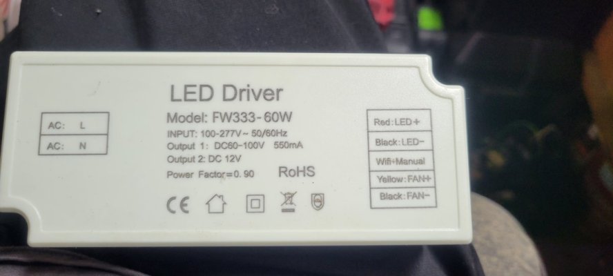
Viparspectra Timer Controlled Reef Light - This is a 165W (I haven't opened up my 300W yet but I'm guessing the internals are basically doubled)
Neptune Apex - Specifically, you need the 0-10V Variable Speed ports. If your ports are occupied or you don't have any (ApexEL) you may need to buy a VDM module.
Steve's LEDs Adapter - I bought the 4-Channel for future expansion.
An Ethernet Cable - If you're good at making your own go right ahead, otherwise buy one or use a spare you've got laying around. Make sure you have enough length as you will need to connect the lights internal wiring to the adapter and the adapter to the Apex.
Tools - A few sizes of Phillips head screwdrivers, basic wiring pliers (data cable tools like this are very helpful)
Let's Get Started
Make sure the light is not plugged into power. Take out the screws along the top of the four sides. (After pulling the top off I put these screws partially back in to avoid losing them and so I could set the top down on the bottom without worrying about damaging anything.) Here's the internals:


Do not assume your wires are the same! Follow these steps to confirm the wire usage!
The black plastic boxes circled in yellow are the driver boxes, there are two of them because one controls each of the lighting channels. We will be opening them up to confirm the usage of the four signal wires going to the controller panel (circled in red). So take those metal straps off of the driver boxes and open them up.
Before you go unplugging things and cutting wires, here's a little side project.

Your driver board hopefully has a dimmer pot like this on it. That MIN-SET text means that this will allow you to tweak the lowest setting for this channel of LEDs. Prop up your light (or have a friend hold it) so that you can plug it into the wall and turn it on. Using the front control panel set the power of each Channel to 1. Now for the tweak. (These are electrical components so don't just go touching things, be conscious of where your hands are). Use a small screwdriver to turn the dial in that dimmer pot. Either your whites or your blues will change in brightness. You've now identified which driver is which, I recommend marking this somewhere in the box (I used blue paint to identify the driver box for the Blue channel). Turn the dial down to the lowest setting that the channel properly functions at. Any lower and it will turn off or flicker. (Your mileage may vary on this. In my experience the lowest setting was the only thing that changed, when I upped the power of the Channel to 2 the brightness jumped up dramatically.)
Now, back to wiring. Turn off the light and make sure you unplug it again.

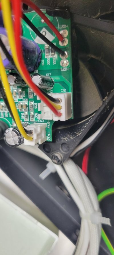
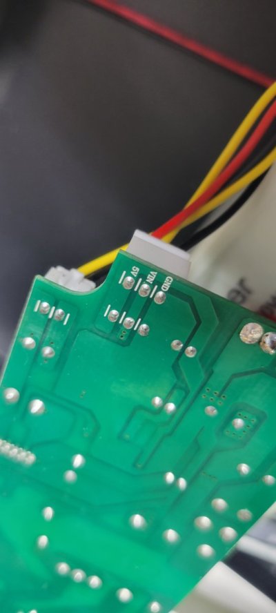
As you can see, the bundle of four wires that connects to the control panel is connected to the driver board in the lime green circle. On this light the gray wire is on the end facing towards the middle of the board so we'll look at the other side of the board to determine what it does:

So on this light the gray is the ground (GND) wire, blue is the PWM signal, brown is the 12V power wire, and white (purple on the other driver) is the On/Off signal. Again, make sure you do this, do not assume your wires are the same as mine. Take a picture or write down your findings for future reference.
Go ahead and put the driver boards back in their boxes and screw everything back down including the metal straps.
Now let's take a look at the adapter. (Pic is from the Neptune thread.)

Let's work our way "down" the driver board layout for the four wires. (You will need to cut and strip jumper wires for these connections.)
The On/Off top wire (Channel 1: White, Channel 2: Purple) are left alone. You will still use the light's timer controls to turn it on and off.
The next wire down is the 12V power line (Channel 1: Brown, Channel 2: Reddish Brown). Pick one and cut it (for reference I took the one from Channel 2, leave the wire from the other driver alone). Take the end coming out of the driver and insert it into the top port in the Vin section on the adapter. The end coming out of the control panel needs to be inserted into the lower port of the Vin section. In the Neptune tutorial the other 12V wire was cut but left unattached to anything, I'm not sure why.
The next wire down is the PWM control wire (Blue for both channels on my light). These wires will need to be cut. The wire coming out of the driver for the White Channel (Channel 1) needs to go into the bottom port on the adapter, labeled "1". The wire coming out of the other driver (Channel 2) goes into port "2" on the adapter. The ends of the PWM wires coming out of the control panel are not connected to anything, because the Apex will now control the light intensity.
The bottom GND ground wires (Gray for both channels on my light) will need to be cut. Take the wires from the drivers, splice them together, and insert them into the upper GND port on the adapter. The wires coming out of the control panel need to be spliced and inserted into the lower GND port on the adapter.
Ports 3 and 4 are empty on this side of the adapter. If you wanted to add another light to this setup port 3 would be Channel 1 and port 4 would be Channel 2 for that light.
Here are some imperfect pictures of my wiring:


Before you move on and forget, plug the 4-wire jacks back into the control panel of the light. I forgot to do this and was so frustrated with the whole thing I left the light sitting in a box for a couple weeks.
The next part is the wiring from the Apex to the Adapter. The plugs on the Apex are RJ45s, otherwise known as ethernet jacks. The variable controls on the Apex are only using half of the ports on the ethernet jack. Here's the orientation:

When I started working on this part I found out there are two standard ways for these RJ45's to be laid out. This seems to be the primary one so as long as the two orange wires are next to each other on one end you should be good. You'll plug one end into the Apex and the other end will be cut and stripped to go into the adapter as shown on the left side of this picture.

Configuring the Apex
Jump on your phone, tablet, or computer and fire up the Apex Fusion app. Unlock your Dashboard screen and add the Variable Speed control tiles to it. Mine were labeled VARSPD1_I1, VARSPD2_I2, etc. The left RJ45 jack on my Apex was ports 1 and 2 and the right jack was ports 3 and 4. I've appropriately relabeled my two used ports.


Unlock one of the used variable speed tiles and Configure it by hitting the gear icon. The All-Important button that it took me a while to find is circled in the second screenshot above. After you hit this it will give you a screen to edit the time markers and power percentages for the channel you are editing. When you are done you will need to do the same for the other channel.
Summary
Everything should be working at this point but that doesn't mean you're done. If you followed this tutorial exactly then you still have a bunch of bare wire connections floating around in that light. It's up to you to figure out what you want to do with those (electrical tape, shrink tubing, etc) along with the best way to set up that adapter and run the ethernet cables. I highly suggest looking through the last post on that Neptune thread (I think I've properly attached it as well). The author has some clever ways to do the wiring and allow you to move lights around and disconnect them. You can also set it up to allow the Apex to turn the channels on and off.
So basically, this tutorial should get you passed the starting line. How far you want to go from here is up to you.

Why "For Dummies"? Well we can't all be experts at everything right? I've had people try to help me with adding ramping controls to a Viparspectra light and God bless them for trying. But here's the thing; we all have different levels of tech savviness. I can build a computer from components, install software, and run a simple Linux OS like Ubuntu; but don't ask me to do my own programming or build my own circuit boards.
So this tutorial is intended to dumb the process down enough to allow almost anyone to follow along. Would I consider the final product to be truly finished? No. But that's not the point here. For the uninitiated these lights can be a bit intimidating when you first open them up. So my goal is to lay down the basics, allow a hobbyist to gain confidence with the process, and point them in the right direction for further improvements.
Some Basics First
Not all "Chinese Black Box" lights are the same and not all lights that are the same brand and model are necessarily the same when you start tearing them apart. At some point during production a component will be changed due to availability or saving 0.4 cents per unit. This is why product recalls are done by serial number range, not just by model number.
Having said that, the basic components and layout are pretty standard. Power input, drivers (the circuit boards), LED panel, fans and/or heat sinks for cooling, and some form of controls like a lighted control board or simply knobs and buttons. This tutorial (although it could be a starting point for other lights) is for the timer controlled Viparspectra lights with front digital control panel. This light uses a PWM signal to turn the LEDs on and off at varying rapid speeds to make the lights look dimmer or brighter. The fact that this light uses a PWM signal is exactly why I struggled to find a good tutorial for what I needed. I found this one on Neptune's forums (a very nice looking "finished product" tutorial has been added to that thread since I found it) and I basically worked off it and added some info to it.
So why is the PWM signal so important? To put it simply, the Apex doesn't work with it. If you use a ReefPi system (what the heck are you doing here, you probably already know a lot more about this stuff than I do) things are a bit simpler because the ReefPi is set up to use PWM components. So to allow the Apex to control the Viparspectra we need to wire in an adapter.
What You Need
Viparspectra Timer Controlled Reef Light - This is a 165W (I haven't opened up my 300W yet but I'm guessing the internals are basically doubled)
Neptune Apex - Specifically, you need the 0-10V Variable Speed ports. If your ports are occupied or you don't have any (ApexEL) you may need to buy a VDM module.
Steve's LEDs Adapter - I bought the 4-Channel for future expansion.
An Ethernet Cable - If you're good at making your own go right ahead, otherwise buy one or use a spare you've got laying around. Make sure you have enough length as you will need to connect the lights internal wiring to the adapter and the adapter to the Apex.
Tools - A few sizes of Phillips head screwdrivers, basic wiring pliers (data cable tools like this are very helpful)
Let's Get Started
Make sure the light is not plugged into power. Take out the screws along the top of the four sides. (After pulling the top off I put these screws partially back in to avoid losing them and so I could set the top down on the bottom without worrying about damaging anything.) Here's the internals:
Do not assume your wires are the same! Follow these steps to confirm the wire usage!
The black plastic boxes circled in yellow are the driver boxes, there are two of them because one controls each of the lighting channels. We will be opening them up to confirm the usage of the four signal wires going to the controller panel (circled in red). So take those metal straps off of the driver boxes and open them up.
Before you go unplugging things and cutting wires, here's a little side project.
Your driver board hopefully has a dimmer pot like this on it. That MIN-SET text means that this will allow you to tweak the lowest setting for this channel of LEDs. Prop up your light (or have a friend hold it) so that you can plug it into the wall and turn it on. Using the front control panel set the power of each Channel to 1. Now for the tweak. (These are electrical components so don't just go touching things, be conscious of where your hands are). Use a small screwdriver to turn the dial in that dimmer pot. Either your whites or your blues will change in brightness. You've now identified which driver is which, I recommend marking this somewhere in the box (I used blue paint to identify the driver box for the Blue channel). Turn the dial down to the lowest setting that the channel properly functions at. Any lower and it will turn off or flicker. (Your mileage may vary on this. In my experience the lowest setting was the only thing that changed, when I upped the power of the Channel to 2 the brightness jumped up dramatically.)
Now, back to wiring. Turn off the light and make sure you unplug it again.
As you can see, the bundle of four wires that connects to the control panel is connected to the driver board in the lime green circle. On this light the gray wire is on the end facing towards the middle of the board so we'll look at the other side of the board to determine what it does:
So on this light the gray is the ground (GND) wire, blue is the PWM signal, brown is the 12V power wire, and white (purple on the other driver) is the On/Off signal. Again, make sure you do this, do not assume your wires are the same as mine. Take a picture or write down your findings for future reference.
Go ahead and put the driver boards back in their boxes and screw everything back down including the metal straps.
Now let's take a look at the adapter. (Pic is from the Neptune thread.)
Let's work our way "down" the driver board layout for the four wires. (You will need to cut and strip jumper wires for these connections.)
The On/Off top wire (Channel 1: White, Channel 2: Purple) are left alone. You will still use the light's timer controls to turn it on and off.
The next wire down is the 12V power line (Channel 1: Brown, Channel 2: Reddish Brown). Pick one and cut it (for reference I took the one from Channel 2, leave the wire from the other driver alone). Take the end coming out of the driver and insert it into the top port in the Vin section on the adapter. The end coming out of the control panel needs to be inserted into the lower port of the Vin section. In the Neptune tutorial the other 12V wire was cut but left unattached to anything, I'm not sure why.
The next wire down is the PWM control wire (Blue for both channels on my light). These wires will need to be cut. The wire coming out of the driver for the White Channel (Channel 1) needs to go into the bottom port on the adapter, labeled "1". The wire coming out of the other driver (Channel 2) goes into port "2" on the adapter. The ends of the PWM wires coming out of the control panel are not connected to anything, because the Apex will now control the light intensity.
The bottom GND ground wires (Gray for both channels on my light) will need to be cut. Take the wires from the drivers, splice them together, and insert them into the upper GND port on the adapter. The wires coming out of the control panel need to be spliced and inserted into the lower GND port on the adapter.
Ports 3 and 4 are empty on this side of the adapter. If you wanted to add another light to this setup port 3 would be Channel 1 and port 4 would be Channel 2 for that light.
Here are some imperfect pictures of my wiring:
Before you move on and forget, plug the 4-wire jacks back into the control panel of the light. I forgot to do this and was so frustrated with the whole thing I left the light sitting in a box for a couple weeks.
The next part is the wiring from the Apex to the Adapter. The plugs on the Apex are RJ45s, otherwise known as ethernet jacks. The variable controls on the Apex are only using half of the ports on the ethernet jack. Here's the orientation:
When I started working on this part I found out there are two standard ways for these RJ45's to be laid out. This seems to be the primary one so as long as the two orange wires are next to each other on one end you should be good. You'll plug one end into the Apex and the other end will be cut and stripped to go into the adapter as shown on the left side of this picture.
Configuring the Apex
Jump on your phone, tablet, or computer and fire up the Apex Fusion app. Unlock your Dashboard screen and add the Variable Speed control tiles to it. Mine were labeled VARSPD1_I1, VARSPD2_I2, etc. The left RJ45 jack on my Apex was ports 1 and 2 and the right jack was ports 3 and 4. I've appropriately relabeled my two used ports.
Unlock one of the used variable speed tiles and Configure it by hitting the gear icon. The All-Important button that it took me a while to find is circled in the second screenshot above. After you hit this it will give you a screen to edit the time markers and power percentages for the channel you are editing. When you are done you will need to do the same for the other channel.
Summary
Everything should be working at this point but that doesn't mean you're done. If you followed this tutorial exactly then you still have a bunch of bare wire connections floating around in that light. It's up to you to figure out what you want to do with those (electrical tape, shrink tubing, etc) along with the best way to set up that adapter and run the ethernet cables. I highly suggest looking through the last post on that Neptune thread (I think I've properly attached it as well). The author has some clever ways to do the wiring and allow you to move lights around and disconnect them. You can also set it up to allow the Apex to turn the channels on and off.
So basically, this tutorial should get you passed the starting line. How far you want to go from here is up to you.
Attachments
Last edited: