I finally got around to getting my doser set up. I was just using a cheap peristaltic pump bolted to a little mounting bracket. It worked fine, but I picked up a Jebao 3 port slave doser for a good price. It was cheaper than buying 3 individual pumps, so I figured why not.
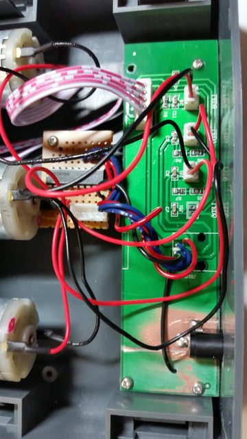
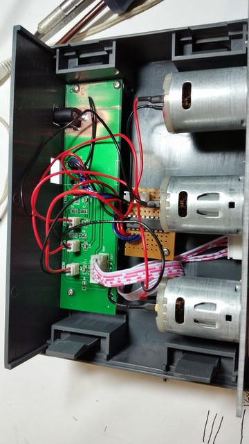
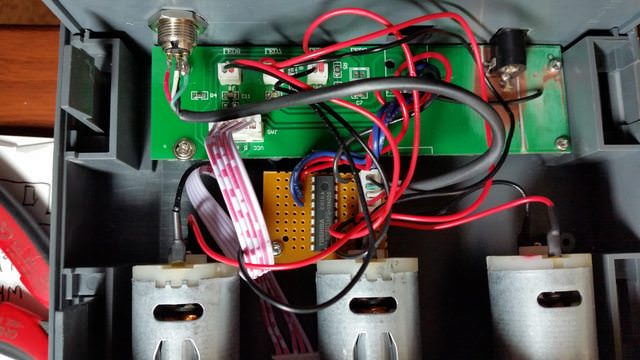
It's pretty simple inside - just 3 dc motors and a board to basically to route the signal power to the pump and light an LED. The unit was designed to receive a 12v PWM signal to drive the motors. I prefer for my reef-pi to only be responsible for generating signals, and leave actual power and power management to the individual devices. I sanded off some of the solder mask, scratched a division to have a 12v copper pour, and tie into the existing ground pour. I added a barrel connector to power the doser and soldered it to the makeshift pads.
I left the motors wired up the way they were, but I replaced the existing signal wires with a ULN2803 so I could drive it from the 3.3v PWM signal from reef-pi. The hacky perf board just holds the ULN2803, JST-XH connector, and wires to inject the signal into the existing traces on the board where I removed the old port.
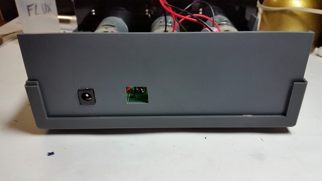
Here's a quick shot of the back before I added the signal connector. I still hate trying to cut square holes, but this one for the barrel connector doesn't look too bad. I just covered up that other hole with a sticker later...
I added a mini-xlr connector (my favorite connector so far!) to interface with reef-pi.
Now that's one more thing moved off the ReefKeeper and over to reef-pi!