Jabeo controlled by apex, without a reef angel cable

trido

Valuable Member
View Badges
Joined
Apr 22, 2010
Messages
1,636
Reaction score
1,062
Location
Lynnwood, Washington
Rating - 0%
0   0   0
I researched as many threads as I can without spending too much time spinning my wheels. I followed this diagram and read through the thread it was in and cant find any details on why i might not work.
Apex-WP40.jpg


When I use my electrical tester I still get a 10VDC reading on the wave input for the Jabeo. Am I doing something wrong?
 
OP
OP
trido

trido

Valuable Member
View Badges
Joined
Apr 22, 2010
Messages
1,636
Reaction score
1,062
Location
Lynnwood, Washington
Rating - 0%
0   0   0
The double resistor is a 1K Ohm 1 Watt pair from Radio Shack. I paid under $3 for each set. The problem is that I still read 10VDC on the input of the Jabeo. I'm not sure if I am using my meter wrong or if the diagram simply doesn't work.
 
OP
OP
trido

trido

Valuable Member
View Badges
Joined
Apr 22, 2010
Messages
1,636
Reaction score
1,062
Location
Lynnwood, Washington
Rating - 0%
0   0   0
I just talked to my boss who is real good at low voltage electrical. He explained that the resistors need to be wired exactly like in the picture. In line, with the hot lead to the Jabeo from in between the two. I wired mine like a"Y". Not the correct way.
 

tony...kokomo

Community Member
View Badges
Joined
Dec 29, 2013
Messages
39
Reaction score
1
Rating - 0%
0   0   0
Can you make another drawing showing what you talking about I just left radio shack lol
 

tony...kokomo

Community Member
View Badges
Joined
Dec 29, 2013
Messages
39
Reaction score
1
Rating - 0%
0   0   0
The part I'm not understanding is one end of resister goes to the +10vdc on apex and the end of other resister goes to the ground.... Won't that harm the apex itself sending part signal back into the neg side of it?
 
OP
OP
trido

trido

Valuable Member
View Badges
Joined
Apr 22, 2010
Messages
1,636
Reaction score
1,062
Location
Lynnwood, Washington
Rating - 0%
0   0   0
The part I'm not understanding is one end of resister goes to the +10vdc on apex and the end of other resister goes to the ground.... Won't that harm the apex itself sending part signal back into the neg side of it?
I'll post a picture of my wiring when I get home and rewire it. It will be around 6:00 Pacific time when I get it done. I'm at work now.
 

Sacohen

Valuable Member
View Badges
Joined
Nov 8, 2012
Messages
1,423
Reaction score
60
Location
Ft. Lauderdale, FL
Rating - 0%
0   0   0
This post has it either with a Reef Angel cable or without.

This is not my work I found it on a New York reef forum.


A Reef Angel Jebao Cable. That's it. No need for the Jebao controller box anymore.
------
or

0-10v analog input PWM module:
Search ebay for LED DIMMER PWM 10 A.12VDC-24 VDC; POT. or 0-10V control
-----------------
Cat5e ethernet cord

Wire nuts
or
Solder and heat shrink tubing

(optional) Solid core wires (or wires that can handle up to 6A) stevesleds.com has some.

Directions:

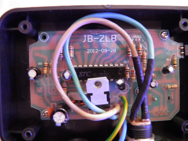
Unscrew the controller casing

P2190005_zps108350d0.jpg


24- is blue
24+ is reddish brown
VA is green yellow and remains untouched

Cut the blue and red wire about halfway down, so you have enough wire connected to the controller still, and some down the cord to the pump. You can also desolder the wires from the 24+ and 24- points, but this is more difficult.

Connect solid core wire to extend the wire length with wire nuts, solder, or some way to connect the wires securely. This makes it easier to work with.

The 0-10v PWM module terminals look like this -+ +-

The first left side -(blue) and +(red) go to the pump wires

The next right side +(red) -(blue) are the ones connected to the controller internals 24+ and 24- points

For the wire to connect to the apex VDM ports, you can buy the Neptune cable ~$15, or do the following.

Cut one end off a Cat 5e ethernet cord.

Keep the following wires:
orange/white wire (positive) - orange wire (negative)
blue/white wire (positive) - green wire (negative)

When plugged into the first VDM port, blue/white wire, green wire is V1, oranges are V2
Second port, blue white green is V3, oranges V4

On the 0-10v module for V1, connect blue/white to + on 0-10v control input terminal , green to - control.

Put the controller back together in a project box, do a really good job with electrical tape taping the loose box together, or fit it all inside somehow and screw back together.

Create profiles to control the pump. The original controller mode are kept, so you can use the Apex to set intensity.

The easiest profiles are ramping profiles throughout the day, like this:

Outlet - Base_Var1 (for V1)

Set PM-Else
If Time 07:00 to 10:00 Then AM-Else
If Time 10:01 to 21:00 Then Day-Else
If Time 21:01 to 23:00 Then PM-Else
If FeedA 000 Then Feed

(feed would be a profile to allow the feed mode)

Profile name: AM-Else

Control type: Ramp

Ramp time (minutes): 1

Start Intensity: 60
End Intensity: 60

(this makes the pump run at 60% power, but if you use the ELSE mode on the controller, it simulates reef crest mode on a vortech, but at 60% overall power)

A midday profile can be made to use a higher intensity, and the PM one can use a lower one.

This barely touches on what can be programmed. If you set the pump on H1 (full power), you can create your own wave mode, like this (borrowed from Kenargo's Tunze profiles)

Profile name: Day Rt
Type: pump
Minimum Intensity: 30
Maximum Intensity: 100
Sync: Enabled
Divide-by 10: Enabled
Initial off time: 4
On time: 8
Off time: 0

Profile name: Day Lt
Type: pump
Minimum Intensity: 30
Maximum Intensity: 100
Sync: Enabled
Divide-by 10: Enabled
Initial off time: 0
On time: 8
Off time: 4

(This creates a huge syncronized wave between two pumps)

You can also use the Weather profiles to control the pump. The Vortech profiles do not work.

If anyone can create other profiles, share!
 
OP
OP
trido

trido

Valuable Member
View Badges
Joined
Apr 22, 2010
Messages
1,636
Reaction score
1,062
Location
Lynnwood, Washington
Rating - 0%
0   0   0
I searched e-bay for the box listed in that post and found them for about the same price as the reef angel connector . Cutting the cord and wiring the resistors isn't as pretty but only costs about Three dollars.
 

tony...kokomo

Community Member
View Badges
Joined
Dec 29, 2013
Messages
39
Reaction score
1
Rating - 0%
0   0   0
How do I get to the set up that offers intensity? Tried advanced just empty below I figured that would be the easy part lol
 
OP
OP
trido

trido

Valuable Member
View Badges
Joined
Apr 22, 2010
Messages
1,636
Reaction score
1,062
Location
Lynnwood, Washington
Rating - 0%
0   0   0
IMG_5629.jpg

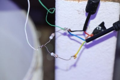
This is the proper wiring configuration for the voltage reduction.
The red from the power supply connects to the Brown on the Jabeo.
The black from the powersupply connects to the Blue on the Jabeo.
The Solid wire (negative) from the Apex (orange or green if your using an ethernet cable) also goes to the black and blue (ground wires).
Now comes the important part.
Solder the two resistors together in a line.
Solder the positive lead (orange/white or blue/white with ethernet) from the apex to one end of the resistors,
Then Solder the other end of the resistors to the Ground wire cluster.
Finally, Solder the yellow/green jabeo wire in between the two resistors.

This wiring configuration will cut the output voltage from the Apex in half. From 10.7VDC down to 5.4VDC

I didn't put any heat shrink tape on this so I could show how its set up easier but will add it later. If you don't have any heat shrink, you could always carefully wrap each connection with electrical tape.

THE FOLLOWING PICTURE IS THE WRONG WAY TO WIRE THIS SET UP UNFORTUNATELY I DON'T KNOW HOW TO REMOVE IT.
 

Attachments

  • IMG_5618.jpg
    IMG_5618.jpg
    79.1 KB · Views: 977
Last edited:

tony...kokomo

Community Member
View Badges
Joined
Dec 29, 2013
Messages
39
Reaction score
1
Rating - 0%
0   0   0
I just ordered the water proof led cord so I won't have to cut any cords to pump at all lol my whole cost now is still under $10
 

tony...kokomo

Community Member
View Badges
Joined
Dec 29, 2013
Messages
39
Reaction score
1
Rating - 0%
0   0   0
They can be done without the resisters as they take the 0-10vdc signal it's just a matter of splicing the cord
 

Bubbles, bubbles, and more bubbles: Do you keep bubble-like corals in your reef?

  • I currently have bubble-like corals in my reef.

    Votes: 61 40.1%
  • I don’t currently have bubble-like corals in my reef, but I have in the past.

    Votes: 17 11.2%
  • I don’t currently have bubble-like corals in my reef, but I plan to in the future.

    Votes: 43 28.3%
  • I don’t currently have bubble-like corals in my reef and have no plans to in the future.

    Votes: 29 19.1%
  • Other.

    Votes: 2 1.3%
Back
Top