reef-pi :: An opensource reef tank controller based on Raspberry Pi.

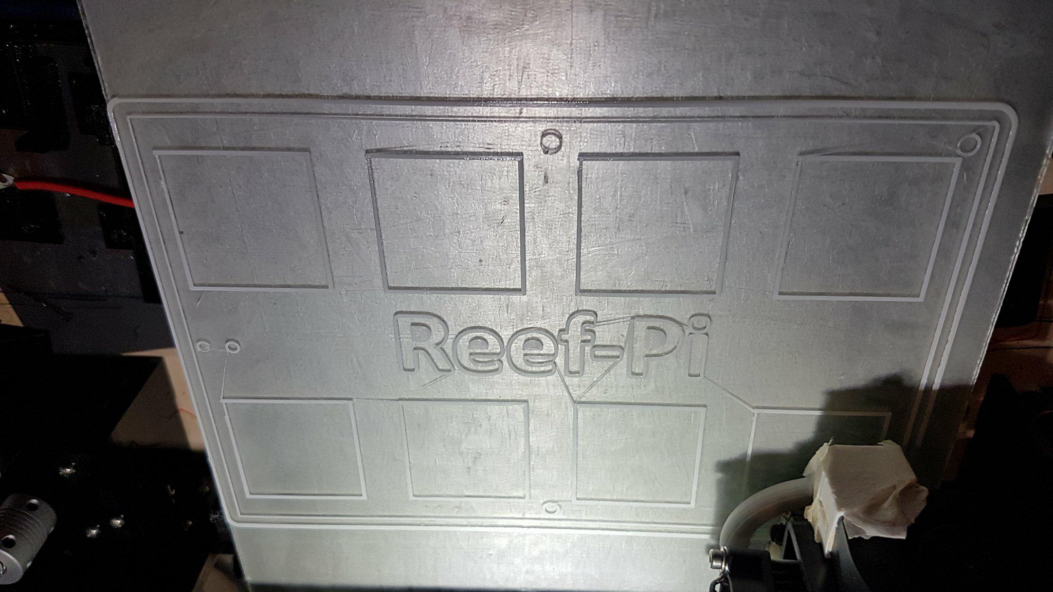
First layer going down :D (pic was mirrored so that the writing reads properly).

The power board is broken up into 4 pieces (Power sockets top, power sockets bottom, relay housing top, relay housing bottom). Each piece will take between 10-16hrs to print and I think I only have enough filament to print 3 of them atm, but I have more already on the way! Once I have printed a whole power board I will upload the STL and F360 files for anyone who may want to use them.

29955400_10156454849624427_243837387_o.jpg

ReefPi Power Board Version 2 v15 2.png
this is a great scratch build :-)
 
First layer going down :D (pic was mirrored so that the writing reads properly).

The power board is broken up into 4 pieces (Power sockets top, power sockets bottom, relay housing top, relay housing bottom). Each piece will take between 10-16hrs to print and I think I only have enough filament to print 3 of them atm, but I have more already on the way! Once I have printed a whole power board I will upload the STL and F360 files for anyone who may want to use them.

29955400_10156454849624427_243837387_o.jpg

ReefPi Power Board Version 2 v15 2.png

Id be interested in printing some of these for people too?
 
Id be interested in printing some of these for people too?
Awesome :) Once I have printed it out and made sure everything works well etc I'll upload all the files to thingiverse.

It uses standard panel mount universal sockets and a fairly cheap 240V-5V power supply to power the relay board (although the power supply is not essential). Only main issue that others might have if printing this out is that the mounting holes I built in for my relay board might be different to the mounting holes of others. My relay boards are very a different shape to everyone else.

Having said that if someone can give me precise measurements for a "standard" relay board I can put in mounting holes for that too. Or when I upload the files someone else can remix them to put the mounting holes wherever they want :)
 
Am getting this after running that command
1522782568270981658222.jpg

Did you run that command ? I just cross checked the timer feature on 1.4 , and it worked as expected . The UI bug was a hiccup though. I’ll fix that in next release
 
Am getting this after running that command
1522782568270981658222.jpg
wrong command, you have to explictly say reef-pi.service, not reef-pi
Code:
-u reef-pi.service
 
@Ranjib Any sneak peak news on your jebao pp-4 and reef pi?
Didn;'t get time one this, i prepared the circuit, but i was blocked on connectors. I need 3 pin DMX style connector for the jebao pump. It will be a month or more before I get back to the wave maker.
 
Part 1 of 4 is done and part 2 is on the way :D

Don't look too closely because there is some minor defects (not too sure what caused some of it but pretty dang good for a $200 printer).
29995921_10156456888389427_381184996_o.jpg
29995529_10156456888404427_1760289739_o.jpg
This is so cool :-)
 
While we are on the power controller theme, I just thought some new developments on my end regarding the power controller.

This is perhaps the easiest thing to build , electronically , and riskiest thing to have , electrically. Particularly around the housing side (where we mount the ac receptacles etc). Phabricating electrically safe (110v ac ) housing is non trivial by most of us. I used wooden and then recently plastic junction box. Though it’s better, I could still feel the risk.
So, recently one of my local reefer (thanks mike ) Pinter out adj power strips. While scouting through them I stumbled upon this little baby , an 8 channel power strip with relays on board and has a db9 connector for external control, for 50$ in Amazon. Voila

Adj srp 8: https://www.amazon.com/gp/aw/d/B01K...AC_SX236_SY340_QL65&keywords=adj+8+pack+relay
srp8.jpg


Close up of the connector (db9, very similar to vga, widely used for serial communications) . Here’s a close up
1AE00094-49E9-40BE-A9F4-A733BAB7A08F.jpeg

Once I opened it up, I noticed it uses a 12 v relay
6611FB45-C392-42A0-9F41-545CBC7573A2.jpeg

One of the connector pin (5) is common across the relays, rest of them used to control individual relays, one pin for every individual relay.

9E9D495B-9439-4388-BDA3-F9D069CA9286.jpeg

6611FB45-C392-42A0-9F41-545CBC7573A2.jpeg


A prototype circuit was build , to convert pi gpio (3.3v) output to relays required input (12v) using a uln2803a (because I had it, else I would use uln2003)
F8D60489-EBB3-4B6D-92E4-FDA24FC87016.jpeg

I also go a connector and cable (db9) and test the whole thing out
7411AC5C-3EF4-442B-BB38-ABC6731BEB05.jpeg


Everything worked as expected :-) . I’ll be changing my circuit to use uln2003 and adafruit perma proto board . But I am delighted to get this working. I can finally stop thinking about this topic . I wanted you I get this sorted before maker faire , so this can be part of then exhibit

 
I signed up here because of this project. I do planted freshwater and currently use an Arduino based controller. My issue with that controller (Hurricane X, the same as a Storm X from Coralux) is that it ramps everything and holds it for the entire day. I want my reds and yellows to fade off after sunrise and I don't have the time or ambition to rewrite the program. I was dragging my feet the other day to add code to turn on solid state relays. I think this will be a better solution for me. Out of interest, have you ever seen the implementation of timelord used in the above mentioned controllers? It's pretty interesting in that you can assign latitude and longitude and allow it to calculate the sunrise and sunset. I ordered a pi and I'm looking forward to building this thing!

Here are some photos of the current setup:

IMAG0043.jpg


IMAG0038.jpg


IMAG0039.jpg
 
I signed up here because of this project. I do planted freshwater and currently use an Arduino based controller. My issue with that controller (Hurricane X, the same as a Storm X from Coralux) is that it ramps everything and holds it for the entire day. I want my reds and yellows to fade off after sunrise and I don't have the time or ambition to rewrite the program. I was dragging my feet the other day to add code to turn on solid state relays. I think this will be a better solution for me. Out of interest, have you ever seen the implementation of timelord used in the above mentioned controllers? It's pretty interesting in that you can assign latitude and longitude and allow it to calculate the sunrise and sunset. I ordered a pi and I'm looking forward to building this thing!

Here are some photos of the current setup:

IMAG0043.jpg


IMAG0038.jpg


IMAG0039.jpg
I don’t have any plan to added geo specific features (lat/long) any time soon. For what it’s worth, adafruit has a gps breakout that I have used in past to get lat/long automatically. I don’t see a lot of value in it, but if there’s enough interest i am happy to reconsider this
Let us know how your build goes, happy to answer any question you have.

And welcome to reef2reef
 
Hey Guys,
Sorry to just jump in here but I just finished my reef-pi build and wanted to post it and see what you guys thought. I am realizing that I didn't make it to the end of this forum before I got so excited about this project and ordered the parts I thought would work. I used a 4 gang plastic electrical box and an 8 channel solid state relay which I mounted inside behind the receptacles. I ran the wires from the raspberrypi 3 through a knockout and riveted a power entry port on the side of the box and plan to add on temp and ph probes later. I wanted to keep everything as low profile as possible but I really like the clear faced enclosures that I am seeing in here.
-Dan
IMG_4835.JPG
IMG_4985.JPG
IMG_4989.JPG
@MaccaPopEye your printed enclosure looks amazing BTW.
 
Hey Guys,
Sorry to just jump in here but I just finished my reef-pi build and wanted to post it and see what you guys thought. I am realizing that I didn't make it to the end of this forum before I got so excited about this project and ordered the parts I thought would work. I used a 4 gang plastic electrical box and an 8 channel solid state relay which I mounted inside behind the receptacles. I ran the wires from the raspberrypi 3 through a knockout and riveted a power entry port on the side of the box and plan to add on temp and ph probes later. I wanted to keep everything as low profile as possible but I really like the clear faced enclosures that I am seeing in here.
-Dan
IMG_4835.JPG
IMG_4985.JPG
IMG_4989.JPG
@MaccaPopEye your printed enclosure looks amazing BTW.
very cool :-) thanks for sharing your build with us. Let us know if you have any question.
And welcome to reef2reef :-)
 
While we are on the power controller theme, I just thought some new developments on my end regarding the power controller.

This is perhaps the easiest thing to build , electronically , and riskiest thing to have , electrically. Particularly around the housing side (where we mount the ac receptacles etc). Phabricating electrically safe (110v ac ) housing is non trivial by most of us. I used wooden and then recently plastic junction box. Though it’s better, I could still feel the risk.
So, recently one of my local reefer (thanks mike ) Pinter out adj power strips. While scouting through them I stumbled upon this little baby , an 8 channel power strip with relays on board and has a db9 connector for external control, for 50$ in Amazon. Voila

Adj srp 8: https://www.amazon.com/gp/aw/d/B01K...AC_SX236_SY340_QL65&keywords=adj+8+pack+relay
srp8.jpg


Close up of the connector (db9, very similar to vga, widely used for serial communications) . Here’s a close up
1AE00094-49E9-40BE-A9F4-A733BAB7A08F.jpeg

Once I opened it up, I noticed it uses a 12 v relay
6611FB45-C392-42A0-9F41-545CBC7573A2.jpeg

One of the connector pin (5) is common across the relays, rest of them used to control individual relays, one pin for every individual relay.

9E9D495B-9439-4388-BDA3-F9D069CA9286.jpeg

6611FB45-C392-42A0-9F41-545CBC7573A2.jpeg


A prototype circuit was build , to convert pi gpio (3.3v) output to relays required input (12v) using a uln2803a (because I had it, else I would use uln2003)
F8D60489-EBB3-4B6D-92E4-FDA24FC87016.jpeg

I also go a connector and cable (db9) and test the whole thing out
7411AC5C-3EF4-442B-BB38-ABC6731BEB05.jpeg


Everything worked as expected :) . I’ll be changing my circuit to use uln2003 and adafruit perma proto board . But I am delighted to get this working. I can finally stop thinking about this topic . I wanted you I get this sorted before maker faire , so this can be part of then exhibit
This is very nice @Ranjib But do they do a UK 240 version? We dont use sissy 115v over here, we're on the hard stuff ;-)
 
Have I missed any updates on the pH probe circuit? I know it's in testing, but is it functional?
 
While we are on the power controller theme, I just thought some new developments on my end regarding the power controller.

This is perhaps the easiest thing to build , electronically , and riskiest thing to have , electrically. Particularly around the housing side (where we mount the ac receptacles etc). Phabricating electrically safe (110v ac ) housing is non trivial by most of us. I used wooden and then recently plastic junction box. Though it’s better, I could still feel the risk.
So, recently one of my local reefer (thanks mike ) Pinter out adj power strips. While scouting through them I stumbled upon this little baby , an 8 channel power strip with relays on board and has a db9 connector for external control, for 50$ in Amazon. Voila

Adj srp 8: https://www.amazon.com/gp/aw/d/B01K...AC_SX236_SY340_QL65&keywords=adj+8+pack+relay
srp8.jpg


Close up of the connector (db9, very similar to vga, widely used for serial communications) . Here’s a close up
1AE00094-49E9-40BE-A9F4-A733BAB7A08F.jpeg

Once I opened it up, I noticed it uses a 12 v relay
6611FB45-C392-42A0-9F41-545CBC7573A2.jpeg

One of the connector pin (5) is common across the relays, rest of them used to control individual relays, one pin for every individual relay.

9E9D495B-9439-4388-BDA3-F9D069CA9286.jpeg

6611FB45-C392-42A0-9F41-545CBC7573A2.jpeg


A prototype circuit was build , to convert pi gpio (3.3v) output to relays required input (12v) using a uln2803a (because I had it, else I would use uln2003)
F8D60489-EBB3-4B6D-92E4-FDA24FC87016.jpeg

I also go a connector and cable (db9) and test the whole thing out
7411AC5C-3EF4-442B-BB38-ABC6731BEB05.jpeg


Everything worked as expected :) . I’ll be changing my circuit to use uln2003 and adafruit perma proto board . But I am delighted to get this working. I can finally stop thinking about this topic . I wanted you I get this sorted before maker faire , so this can be part of then exhibit



That's awesome, looking forward to the official build on the reef pi website. What software do you use to diagram the fritz diagrams?

 

ARE YOU READY TO CONFESS TO CRAZIEST, DUMBEST, FUNNIEST THING YOU’VE EVER DONE IN REEFING?

  • Yeah, I'll confess! (Share your story in the comments!)

    Votes: 26 65.0%
  • Nah, I'll keep mine a secret...(Don't be like that, share with the class!)

    Votes: 14 35.0%
Back
Top
Home
Post thread…
Market
What's new