reef-pi :: An opensource reef tank controller based on Raspberry Pi.

OP
OP
Ranjib

Ranjib

7500 Club Member
View Badges
Joined
Apr 16, 2016
Messages
9,843
Reaction score
17,058
Location
Pleasant Hill, Concord
Rating - 0%
0   0   0
@Ranjib , quick question please. My "lighting" tab has just disappeared. Tried reinstalling over the top but no go. Before I purge and reinstall I thought that I'd ask if the tab would be displayed whether or not the PMW (kessil) hardware is there. I want to rule out a hardware failure.
Cross check your settings: Configuration -> setting -> capabilities. Lighting should be enabled there. If its still not in the UI, then likely something is wrong,

ssh into pi, check reef-pi log in one tab and restart reef-pi service. It should say why its not enabling the lighting module

Code:
sudo systemctl -fu reef-pi.service # in one tab, to see the logs
sudo systemctl restart reef-pi.service # to trigger restart of the reef-pi service.

The initial log statement soon after the restart is important, they should enumerate all the modules reef-pi is enabling/disabling
 
OP
OP
Ranjib

Ranjib

7500 Club Member
View Badges
Joined
Apr 16, 2016
Messages
9,843
Reaction score
17,058
Location
Pleasant Hill, Concord
Rating - 0%
0   0   0
Greetings everyone! I recently put together a tc reef-pi build and it was a lot fun. This was my first time doing anything with a Raspberry pi or linux and everything went along smoothly thanks to the build guides and everyone on this thread.

I'm having an issue with telemetry. On adafuit, only the default created system-load5 and system-mem-used feeds are getting data. How can I get the temperature feed to work? feed.JPG dash.JPG
The adfruit integration is broken in the 2.0 beta builds.. I am thinking on how to best address this. The volume of telemetry data reef-pi generates (since 2.0 support multiple ato, ph and temp sensors) is simply above the normal free tier usage. ,, either I have to make it customizable and allow only selected probes to send data (even in that case user have to be aware of it), or just remove it , or let users know that they need paid account (and that too has a limit)
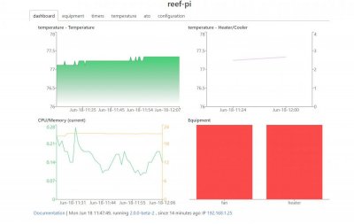
For the time being, use the built in dashboard till we sort this out
 
OP
OP
Ranjib

Ranjib

7500 Club Member
View Badges
Joined
Apr 16, 2016
Messages
9,843
Reaction score
17,058
Location
Pleasant Hill, Concord
Rating - 0%
0   0   0
Screenshot from 2018-06-19 14-50-07.png Hi to all again. What do i do wrong what is wrong with network.
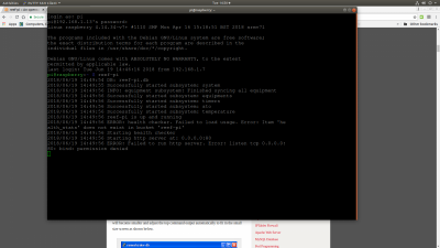
ah.. you are running reef-pi as normal users, which can not bind to port 80. To start reef-pi do this instead
Code:
sudo systemctl start reef-pi.service
 
OP
OP
Ranjib

Ranjib

7500 Club Member
View Badges
Joined
Apr 16, 2016
Messages
9,843
Reaction score
17,058
Location
Pleasant Hill, Concord
Rating - 0%
0   0   0
As said above it's under-powered / inconsistent power, apparently it can be bad to run the Pi when it is showing that symbol.

I got the same symbol when I tried to power the Pi using a LM2596 and when using the Pi with a display (not sure if the same power issues occured without a display as I can't see the lightning bolt :p)

The LM2596 can provide up to 3A (I think) and I was using an 8A 12V power supply stepped down to 5V so it should have had ample current so I can only assume it was caused by the irregular supply issues that Ranjib has been investigating recently. To fix this I've now got some dedicated 240V AC to 5V DC 3A (they were also advertised as 'low ripple EMI isolated' whatever that means :p) converters that I am going to test out (haven't tested them yet though)
LM2596 based setup works , except for the rpi based pwm output. i.e. it is ok to use ato sensor, ph, pca9685 with lm2596. Remember to connect everything with the same power rails.. i.e. lm2596 should hook up to a 5v power rail, and pi, pca9685, ph sensor etc all connects to that, and not to use Pi's GPIO to power other breakout boards.

The PWM jitter effect as visible in oscilloscope (from my earlier post) , only relevant for led dimming via Pi hardware, for all other cases lm2596 based approach works. In fact all my builds except one is powered by at least one (sometime two) lm2596 module.
 
OP
OP
Ranjib

Ranjib

7500 Club Member
View Badges
Joined
Apr 16, 2016
Messages
9,843
Reaction score
17,058
Location
Pleasant Hill, Concord
Rating - 0%
0   0   0
OK. More info on my lighting problem-

As stated before, I have 5 dimmable channels of 12VDC currently run by a TC420.

I tried to change them over to the schematic that Ranjib gave me above. I got it to sort of work for a few few minutes and then it stopped with a pop sound from the "Reef-Pi" area. Some investigation found the ULN 2803 to be very hot, so I needed to get another. Checking and double checking, found another amateur mistake. I had connected the output from the PCA9685 from the PWM poles instead of Gnd. I changed that, installed a new ULN 2803 and tried again. Now the lights just flash - frequency roughly once per second. I even tried changing the channels on the PCA9685 and the same thing.

Question :- Did my error on the connection to the PCA9685 possibly cook it? Did I cook the PWM on the Pi?

My thinking is to try connect one channel of lights to the PWM signal directly from the Pi to see if that is working. If it does, my guess is that the PCA9685 needs replacing (such is the cost of school fees). BUT, I can't find a guide to connecting lights directly to the PWM signal directly from the Pi. Also, thinking about it, I'd like to try get the two PWM channels available direct off the Pi working as a temporary measure.

Any advice anyone?

On a side note, I have 4 pieces of equipment and the ATO working perfectly and I'm very happy. Just waiting for my temp probe to arrive and then once I have the lighting going I'll start thinking about PH and dosing.
You have to know what the current draw of your LEDs. ULN2803 has a limit on overall current draw (i think its less than 1.5A), above which you'll fry the chip. I can use logic level power mosfet (cheapest), or meanwell drivers (costliest, but best in quality) for higher amp LEDs
 
OP
OP
Ranjib

Ranjib

7500 Club Member
View Badges
Joined
Apr 16, 2016
Messages
9,843
Reaction score
17,058
Location
Pleasant Hill, Concord
Rating - 0%
0   0   0
OK. More info on my lighting problem-

As stated before, I have 5 dimmable channels of 12VDC currently run by a TC420.

I tried to change them over to the schematic that Ranjib gave me above. I got it to sort of work for a few few minutes and then it stopped with a pop sound from the "Reef-Pi" area. Some investigation found the ULN 2803 to be very hot, so I needed to get another. Checking and double checking, found another amateur mistake. I had connected the output from the PCA9685 from the PWM poles instead of Gnd. I changed that, installed a new ULN 2803 and tried again. Now the lights just flash - frequency roughly once per second. I even tried changing the channels on the PCA9685 and the same thing.

Question :- Did my error on the connection to the PCA9685 possibly cook it? Did I cook the PWM on the Pi?

My thinking is to try connect one channel of lights to the PWM signal directly from the Pi to see if that is working. If it does, my guess is that the PCA9685 needs replacing (such is the cost of school fees). BUT, I can't find a guide to connecting lights directly to the PWM signal directly from the Pi. Also, thinking about it, I'd like to try get the two PWM channels available direct off the Pi working as a temporary measure.

Any advice anyone?

On a side note, I have 4 pieces of equipment and the ATO working perfectly and I'm very happy. Just waiting for my temp probe to arrive and then once I have the lighting going I'll start thinking about PH and dosing.
Every time some thing like this happens, I would recommend troubleshooting it step by step. i.e. unplug the LED, but keep rest of the things hooks up, and then use multimeter to check if the voltages are what you expect (pca9685 for example), as you change the values via reef-pi UI
 

philshel

Active Member
View Badges
Joined
Jul 24, 2010
Messages
364
Reaction score
381
Rating - 0%
0   0   0
Cross check your settings: Configuration -> setting -> capabilities. Lighting should be enabled there. If its still not in the UI, then likely something is wrong,

ssh into pi, check reef-pi log in one tab and restart reef-pi service. It should say why its not enabling the lighting module

Code:
sudo systemctl -fu reef-pi.service # in one tab, to see the logs
sudo systemctl restart reef-pi.service # to trigger restart of the reef-pi service.

The initial log statement soon after the restart is important, they should enumerate all the modules reef-pi is enabling/disabling

Actually, before I saw your reply I did several hard reboots and on the forth one it came back. I was just going to tell you to never mind when I saw that you had answered. I have been having issues with needing to pull the power about every week since I switched to a pi zero. The whole thing will freeze and the lights won't shut down (that's how I notice there's an issue) and only pulling the power will get it going again. I wonder if there is an issue with the pi or the power source? Still on 1.3 by the way as right now it's just controlling my lights.
 
OP
OP
Ranjib

Ranjib

7500 Club Member
View Badges
Joined
Apr 16, 2016
Messages
9,843
Reaction score
17,058
Location
Pleasant Hill, Concord
Rating - 0%
0   0   0
Q to Ranjib, would be a mistake to install everything in one box.Like a PC case.Or the relay should be separate.Thank you
I dont think theres a perfect answer that fits everyone's setup. I personally build the controller with a single dc (barrel jack) source, put all electrnics in a transparent top project box (from uxcell), and velcro it in the wall, behind the tank. I can see it, its relatively easier to take out or reinstall, and the power bar is inside the cabinet, with all other equipment plugged in there, while the sensors are connected to the housing (audio jacks). The whole thing kinda look nice. But this is a nano tank and pico tank setup. I can totally see reusing a whole PC housing, i.e. a ATX cabinet to house everything, may be even use a standard 400 watt SMPS to power the build.
 
OP
OP
Ranjib

Ranjib

7500 Club Member
View Badges
Joined
Apr 16, 2016
Messages
9,843
Reaction score
17,058
Location
Pleasant Hill, Concord
Rating - 0%
0   0   0
Q to Ranjib, would be a mistake to install everything in one box.Like a PC case.Or the relay should be separate.Thank you
I would recommend separating the relays if possible though. Mostly because its 110V AC things, and I worry those who are not super familiar might injure themselves. .. i.e. stakes are high... but if you are comfortable (I was) go for it. The fact that you can then use more than 8 (say 16) oulets is nice. Also in some part of the world (i think pretty much everywhere outside USA), you dont have any choice.
 

Des Westcott

Well-Known Member
View Badges
Joined
May 29, 2018
Messages
646
Reaction score
1,035
Location
Durban - South Africa
Rating - 0%
0   0   0
You have to know what the current draw of your LEDs. ULN2803 has a limit on overall current draw (i think its less than 1.5A), above which you'll fry the chip. I can use logic level power mosfet (cheapest), or meanwell drivers (costliest, but best in quality) for higher amp LEDs

1.5A total? Well, I'm pretty sure that's what did it then. It didn't cross my mind to check the current.

Could you please help me out with parts and wiring to set up either of the other two solutions?

Thank you so much for the help so far. I'm really enjoying this journey.
 
OP
OP
Ranjib

Ranjib

7500 Club Member
View Badges
Joined
Apr 16, 2016
Messages
9,843
Reaction score
17,058
Location
Pleasant Hill, Concord
Rating - 0%
0   0   0
1.5A total? Well, I'm pretty sure that's what did it then. It didn't cross my mind to check the current.

Could you please help me out with parts and wiring to set up either of the other two solutions?

Thank you so much for the help so far. I'm really enjoying this journey.
Can you remind me which LED you are using. I need the current draw and voltage in particular. I belive theres a meanwell LDD-L series that will do the job. We have to check for three things
- Voltage rating
- Current draw
- PWM controllable (5v)
 

Des Westcott

Well-Known Member
View Badges
Joined
May 29, 2018
Messages
646
Reaction score
1,035
Location
Durban - South Africa
Rating - 0%
0   0   0
Can you remind me which LED you are using. I need the current draw and voltage in particular. I belive theres a meanwell LDD-L series that will do the job. We have to check for three things
- Voltage rating
- Current draw
- PWM controllable (5v)

They are pretty much DIY LED's - bought in kit form from a local supplier here in SA.

  • They are 12V
  • From what I can tell, it looks like each channel (5 of them) are .5A each
  • From what I can tell, I thought they were PWM controllable. But they are currently controlled by the TC420. I'm trying to figure out how the TC40 works, But the more i get to understand about this stuff, I don't think the TC420 puts out a PWM signal. It receives a 12V supply, stores the program on board and puts out 5 x 0-12V signals to run the LED drivers. The more I think about it, there is my problem right there. (insert forehead slap here!)
So after my stupidity, can you suggest a solution? While the lights work fine on the TC40, I'd like to move everything on that tank to the Reef-Pi as I think it's awesome!

Thanks again for your patience.
 

sjeff35

Active Member
View Badges
Joined
Jun 14, 2018
Messages
172
Reaction score
356
Location
Corrales, NM
Rating - 0%
0   0   0
@Ranjib

Thanks for this system. Just getting started with it this. I have a little experience with Pi.

I was able to setup a temp monitor last night with the parts I had around. I'm trying to setup the Telemetry now with Gmail and adafruit. Are the AIO Key and the Gmail password supposed to be stored? Mine keeps disappearing and I can't get data to show up on the adafruit dashboard. (Note, these are not the actual values i have)

Thanks

upload_2018-6-22_8-11-37.png
 
OP
OP
Ranjib

Ranjib

7500 Club Member
View Badges
Joined
Apr 16, 2016
Messages
9,843
Reaction score
17,058
Location
Pleasant Hill, Concord
Rating - 0%
0   0   0
@Ranjib

Thanks for this system. Just getting started with it this. I have a little experience with Pi.

I was able to setup a temp monitor last night with the parts I had around. I'm trying to setup the Telemetry now with Gmail and adafruit. Are the AIO Key and the Gmail password supposed to be stored? Mine keeps disappearing and I can't get data to show up on the adafruit dashboard. (Note, these are not the actual values i have)

Thanks

upload_2018-6-22_8-11-37.png
They are stored , but will never be visible in the UI. Thats by design, and for security reasons. I can see how thats confusing to users, I would think about some way to make this bit better.

The adafruit integration is broken in 2.0 beta release, i plan to address this in coming weeks. Use the built-in dashboard for the time being
 

sjeff35

Active Member
View Badges
Joined
Jun 14, 2018
Messages
172
Reaction score
356
Location
Corrales, NM
Rating - 0%
0   0   0
They are stored , but will never be visible in the UI. Thats by design, and for security reasons. I can see how thats confusing to users, I would think about some way to make this bit better.

The adafruit integration is broken in 2.0 beta release, i plan to address this in coming weeks. Use the built-in dashboard for the time being


Thanks!!! Makes sense now!
 

Algae invading algae: Have you had unwanted algae in your good macroalgae?

  • I regularly have unwanted algae in my macroalgae.

    Votes: 35 34.0%
  • I occasionally have unwanted algae in my macroalgae.

    Votes: 22 21.4%
  • I rarely have unwanted algae in my macroalgae.

    Votes: 9 8.7%
  • I never have unwanted algae in my macroalgae.

    Votes: 6 5.8%
  • I don’t have macroalgae.

    Votes: 28 27.2%
  • Other.

    Votes: 3 2.9%
Back
Top