


Use some other gpio pin instead of 18 if possible (its used for pwm/light control).
Specify the GPIO pin number in the ato ui
Getting excited. Thanks for everyone and all the great posts and tech advice!
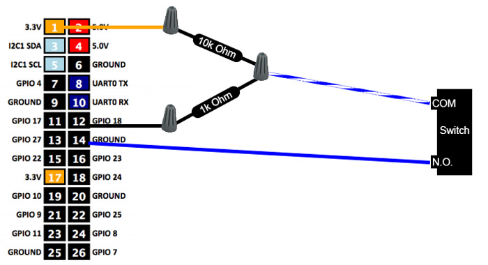
This is next tomorrow. I’m using a mechanical float switch. I have seen a couple diagrams. This one with two resistors.... I have seen one with a 10k “pull down” resistor from the GPIO input to ground and the other end of the switch to 5 volts..... and I also have heard one person using one end of the switch direct to the GPIO input and the other to 3.3v.
Which is recommended and why?