reef-pi :: An opensource reef tank controller based on Raspberry Pi.

b4tn

Valuable Member
View Badges
Joined
Jun 17, 2015
Messages
1,673
Reaction score
2,241
Location
Columbia MD
Rating - 0%
0   0   0
Interesting. I will have to look into it. There is another thread

https://www.reef2reef.com/threads/diy-gyre-controller-idea.295784/

I’m curious if this is the same chip from the eBay board in that thread. I’m just knowledgeable enough with electronics to be dangerous (very basic lol) from what I understand they will work and drive the motors but need tuning to be fully efficient. Thanks for the link.
 

crusso1993

7500 Club Member
View Badges
Joined
Oct 21, 2018
Messages
8,671
Reaction score
44,649
Location
SW, FL, USA
Rating - 0%
0   0   0
Understand, btw thats a massive heat sink on that board, wow! 50v, thats starting to get to where you really need to be more careful.

:)

Nahhh... only if you stick your tongue on it! It's not the volts but the amps. ;)
 

dmolavi

Well-Known Member
View Badges
Joined
Jan 3, 2015
Messages
509
Reaction score
644
Location
United States
Rating - 0%
0   0   0
I've noticed some weirdness in how Adafruit IO displays the ATO "on time". Instead of being in seconds, their graphing engine appears to do some sort of division, so that a 5 or 10 second on time equates to some fraction. It's not consistent, either.

The attached shots show that a 40 second run time got cut down to 1.333 on IO....

Anyone else seeing this, and if so, how can I correct it?
Screenshot_20190511-101134_Chrome.jpeg
Screenshot_20190511-101253_Chrome.jpeg
 

bishoptf

Valuable Member
View Badges
Joined
Jan 1, 2019
Messages
1,344
Reaction score
1,722
Location
Missouri
Rating - 0%
0   0   0
Nahhh... only if you stick your tongue on it! It's not the volts but the amps. ;)

Its really both, since our skin normally has a very high resistance, dry skin for the most part, but that is where voltage comes into play. Lower the resistance and increase the voltage and you have a very bad combination. Doesn't take much of either under the right conditions ( ~100ma will stop the heart) but that is why they consider 50V starting to be considered higher voltage.

I found this at some point in time and I think its a very eye opening read - https://www.dribin.org/dave/blog/archives/2003/12/29/amps_vs_volts/

ooh I forgot this one also - https://www.asc.ohio-state.edu/physics/p616/safety/fatal_current.html

and this one - https://www.allaboutcircuits.com/textbook/direct-current/chpt-3/ohms-law-again/
 
Last edited:

crusso1993

7500 Club Member
View Badges
Joined
Oct 21, 2018
Messages
8,671
Reaction score
44,649
Location
SW, FL, USA
Rating - 0%
0   0   0
Its really both, since our skin normally has a very high resistance, dry skin for the most part, but that is where voltage comes into play. Lower the resistance and increase the voltage and you have a very bad combination. Doesn't take much of either under the right conditions ( ~100ma will stop the heart) but that is why they consider 50V starting to be considered higher voltage.

I found this at some point in time and I think its a very eye opening read - https://www.dribin.org/dave/blog/archives/2003/12/29/amps_vs_volts/

ooh I forgot this one also - https://www.asc.ohio-state.edu/physics/p616/safety/fatal_current.html

:)

I cannot talk about these things without thinking of this guy...

image.jpg
 

Schreiber

Leviathan
View Badges
Joined
Jun 28, 2016
Messages
468
Reaction score
593
Location
Knoxville
Rating - 0%
0   0   0
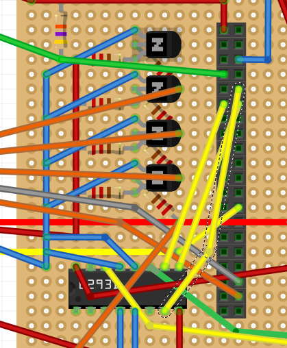
I've got everything hooked up for dosing now & it doesn't wan't to trigger for calibration :( I've tested the pump & it definitely works. Is there a certain voltage I could check on my output pins to see if everything is connected properly?

I've got GPIO 15 & 17 set as the equipment outlets & GPIO 18 as the jack (pin 0 for dosing setup).

Here is my diagram, with the green & yellow wires going off to the bottom right hooked into the motor.


Uploading it won't work, so here's a link to my diagram: https://imgur.com/Pf2IgH8
 
Last edited:
OP
OP
Ranjib

Ranjib

7500 Club Member
View Badges
Joined
Apr 16, 2016
Messages
9,843
Reaction score
17,058
Location
Pleasant Hill, Concord
Rating - 0%
0   0   0
I've noticed some weirdness in how Adafruit IO displays the ATO "on time". Instead of being in seconds, their graphing engine appears to do some sort of division, so that a 5 or 10 second on time equates to some fraction. It's not consistent, either.

The attached shots show that a 40 second run time got cut down to 1.333 on IO....

Anyone else seeing this, and if so, how can I correct it?
Screenshot_20190511-101134_Chrome.jpeg
Screenshot_20190511-101253_Chrome.jpeg
I think the ato graph has some weirdness in reef-pi app as well. I’ll be looking into this now, since I’m just wrapping up the calibration work.
@Zekth if you have time, let’s catch up on the ui bits for supporting the new calibration api. It’s backend complete now (or that’s what I think :) )
 
OP
OP
Ranjib

Ranjib

7500 Club Member
View Badges
Joined
Apr 16, 2016
Messages
9,843
Reaction score
17,058
Location
Pleasant Hill, Concord
Rating - 0%
0   0   0
I've got everything hooked up for dosing now & it doesn't wan't to trigger for calibration :( I've tested the pump & it definitely works. Is there a certain voltage I could check on my output pins to see if everything is connected properly?

I've got GPIO 15 & 17 set as the equipment outlets & GPIO 18 as the jack (pin 0 for dosing setup).

Here is my diagram, with the green & yellow wires going off to the bottom right hooked into the motor.

Missing diagram. Can you share the screenshot of equipment, doser and connectors page as well. I’m just using the same mechanism for ato
 

Schreiber

Leviathan
View Badges
Joined
Jun 28, 2016
Messages
468
Reaction score
593
Location
Knoxville
Rating - 0%
0   0   0
Missing diagram. Can you share the screenshot of equipment, doser and connectors page as well. I’m just using the same mechanism for ato

I've got a link to my diagram on the original question now since uploading it didn't work.

Here's the diagram:
Pf2IgH8.png


Here's the equipment page:
upload_2019-5-11_17-34-35.png


Dosing:
upload_2019-5-11_17-36-54.png


Connectors:
upload_2019-5-11_17-37-24.png
 
OP
OP
Ranjib

Ranjib

7500 Club Member
View Badges
Joined
Apr 16, 2016
Messages
9,843
Reaction score
17,058
Location
Pleasant Hill, Concord
Rating - 0%
0   0   0
ph driver is running smoothly for almost a week now, here is the chart of uncalibrated reading (in millivolts )
Screen Shot 2019-05-11 at 1.42.00 PM.png


I just merged the calibration code in master, rolling it out on my test builds as I write this post. I'll keep a watch on how it performs.
My consolidated dashboard for the pico tank, notice the ATO dashboard is not quite right, im not sure if its due to the pometheus integration or a bug in ato charting logic itself, the in-app dashboard looks ok.
Screen Shot 2019-05-11 at 1.42.10 PM.png
 

Creating a strong bulwark: Did you consider floor support for your reef tank?

  • I put a major focus on floor support.

    Votes: 54 40.3%
  • I put minimal focus on floor support.

    Votes: 28 20.9%
  • I put no focus on floor support.

    Votes: 48 35.8%
  • Other.

    Votes: 4 3.0%
Back
Top