reef-pi :: An opensource reef tank controller based on Raspberry Pi.

I've got everything hooked up for dosing now & it doesn't wan't to trigger for calibration :( I've tested the pump & it definitely works. Is there a certain voltage I could check on my output pins to see if everything is connected properly?

I've got GPIO 15 & 17 set as the equipment outlets & GPIO 18 as the jack (pin 0 for dosing setup).

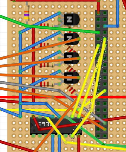
Here is my diagram, with the green & yellow wires going off to the bottom right hooked into the motor.


Uploading it won't work, so here's a link to my diagram: https://imgur.com/Pf2IgH8
 
Last edited:
I've noticed some weirdness in how Adafruit IO displays the ATO "on time". Instead of being in seconds, their graphing engine appears to do some sort of division, so that a 5 or 10 second on time equates to some fraction. It's not consistent, either.

The attached shots show that a 40 second run time got cut down to 1.333 on IO....

Anyone else seeing this, and if so, how can I correct it?

Screenshot_20190511-101134_Chrome.jpeg
Screenshot_20190511-101253_Chrome.jpeg
I think the ato graph has some weirdness in reef-pi app as well. I’ll be looking into this now, since I’m just wrapping up the calibration work.
@Zekth if you have time, let’s catch up on the ui bits for supporting the new calibration api. It’s backend complete now (or that’s what I think :-) )
 
I've got everything hooked up for dosing now & it doesn't wan't to trigger for calibration :( I've tested the pump & it definitely works. Is there a certain voltage I could check on my output pins to see if everything is connected properly?

I've got GPIO 15 & 17 set as the equipment outlets & GPIO 18 as the jack (pin 0 for dosing setup).

Here is my diagram, with the green & yellow wires going off to the bottom right hooked into the motor.

View attachment 1068590
Missing diagram. Can you share the screenshot of equipment, doser and connectors page as well. I’m just using the same mechanism for ato
 
Missing diagram. Can you share the screenshot of equipment, doser and connectors page as well. I’m just using the same mechanism for ato

I've got a link to my diagram on the original question now since uploading it didn't work.

Here's the diagram:
Pf2IgH8.png


Here's the equipment page:
upload_2019-5-11_17-34-35.png


Dosing:
upload_2019-5-11_17-36-54.png


Connectors:
upload_2019-5-11_17-37-24.png
 
ph driver is running smoothly for almost a week now, here is the chart of uncalibrated reading (in millivolts )
Screen Shot 2019-05-11 at 1.42.00 PM.png


I just merged the calibration code in master, rolling it out on my test builds as I write this post. I'll keep a watch on how it performs.
My consolidated dashboard for the pico tank, notice the ATO dashboard is not quite right, im not sure if its due to the pometheus integration or a bug in ato charting logic itself, the in-app dashboard looks ok.
Screen Shot 2019-05-11 at 1.42.10 PM.png
 
I've got a link to my diagram on the original question now since uploading it didn't work.

Here's the diagram:
Pf2IgH8.png


Here's the equipment page:
upload_2019-5-11_17-34-35.png


Dosing:
upload_2019-5-11_17-36-54.png


Connectors:
upload_2019-5-11_17-37-24.png
Wiring and setup looks ok. Can you share the dosing tab's screenshot?
 
It's in the post, right under the equipment. The pump is "kalk pump".
Sorry i missed that. What happens when you run calibration at speed 50 for 10 seconds? Can you check the log and take reading with multimeter on the l293d pwm and in1/in2 pins?
 
Sorry i missed that. What happens when you run calibration at speed 50 for 10 seconds? Can you check the log and take reading with multimeter on the l293d pwm and in1/in2 pins?

Nothing happens with the motor at any settings.

I actually think I figured out what it is after looking up the pinout for the l293d. I'm only running one dosing pump, so only 2 GPIOs, rather than 4 like the guide.

I have them hooked into In 2 & 3. Out 4 & Out 3 go to the motor& En 2 is my PWM. I should've looked at the pinout before making changes. I had just assumed motor 1 & 2's wiring was separated by a short symmetry line between the driver's pin 4 & 5. It looks like its inputs are symmetrical along its length between pins 1 & 9.

I'll check the log tomorrow morning, it's 1:00 a.m. here & I really don't feel like crawling under my desk again to swap the HDMI cord from my computer right now, haha. I'll re-wire tomorrow & report back.
 
Here's my log:

-- Logs begin at Sun 2019-05-12 10:17:01 EDT. --
May 12 12:12:13 Control reef-pi[235]: 2019/05/12 12:12:13 health check: Used memory: 48.85 Load5: 0.45
May 12 12:13:13 Control reef-pi[235]: 2019/05/12 12:13:13 health check: Used memory: 51.51 Load5: 0.89
May 12 12:14:10 Control reef-pi[235]: 2019/05/12 12:14:10 doser subsystem: calibration run for: Kalk Pump
May 12 12:14:10 Control reef-pi[235]: 2019/05/12 12:14:10 Setting pwm driver: rpi pin: 0 value: 50
May 12 12:14:13 Control reef-pi[235]: 2019/05/12 12:14:13 health check: Used memory: 45.88 Load5: 1.34
May 12 12:14:33 Control reef-pi[235]: 2019/05/12 12:14:33 doser subsystem: calibration run for: Kalk Pump
May 12 12:14:33 Control reef-pi[235]: 2019/05/12 12:14:33 Setting pwm driver: rpi pin: 0 value: 50
May 12 12:15:13 Control reef-pi[235]: 2019/05/12 12:15:13 health check: Used memory: 46.71 Load5: 1.23
May 12 12:15:15 Control reef-pi[235]: 2019/05/12 12:15:15 doser subsystem: calibration run for: Kalk Pump
May 12 12:15:15 Control reef-pi[235]: 2019/05/12 12:15:15 Setting pwm driver: rpi pin: 0 value: 50
May 12 12:16:13 Control reef-pi[235]: 2019/05/12 12:16:13 health check: Used memory: 46.73 Load5: 1.17

As far as multimeter readings go, I'm on In 3 & 4, rather than 1 & 2. I'm using Enable 3,4 for the PWM.

At pin #9 (Enable 3,4) I'm getting a constant ~1.54 volts, whether I'm running the calibration or not.

At pin #10 (In 3), I'm getting a constant ~3.3 volts, whether I'm running the calibration or not.

At pin #11 & #14 (Out 3 & 4), I'm getting a constant ~1.8 volts, whether I'm running cal or not.

At pin # 15 (In 4), I'm getting a constant ~1.45 volts, whether I'm running cal or not.

Something...concerning is that when I check the 4 ground pins on the driver, with one lead on the ground bus on my circuit & one lead on a ground pin on the driver, I'm seeing a voltage of ~ 2.4 volts. I'm going to investigate that, may have a stray strand of power wire making contact. I have all 4 ground pins wired in series, so if one is seeing power, they all are.
 
Wow, it's been a long day. Every time I fix an issue, another crops up. Now it looks like my buck converters aren't working. When I power the system up, they emit a high pitched whine for a few seconds, then the LEDs start flashing. Anyone ever seen that?

I'm pretty sure most of my issues have been caused by using stranded wire I already had as jumpers. Stray strands are wreaking havoc in such close quarters. I've got a pack of solid core wire coming in Tuesday & I'm starting from scratch. Learn from my mistakes, stay away from stranded, lol.
 
Last edited:
Wow, it's been a long day. Every time I fix an issue, another crops up. Now it looks like my buck converters aren't working. When I power the system up, they emit a high pitched whine for a few seconds, then the LEDs start flashing. Anyone ever seen that?

I'm pretty sure most of my issues have been caused by using stranded wire I already had as jumpers. Stray strands are wreaking havoc in such close quarters. I've got a pack of solid core wire coming in Tuesday & I'm starting from scratch. Learn from my mistakes, stay away from stranded, lol.
Yep had same issue u need new ones which are quality.
 
Just merged the support ph driver for pico base board from @theatrus in reef-pi master . I know a handful of folks who are using this. It’s been running for a few hours now, without any issue. Here is a side by sa de comparison of the same tank with ph board ,
A0D98D51-D85C-48D8-B0CC-3F782D456C96.png
so far so good.
 
Just merged the support ph driver for pico base board from @theatrus in reef-pi master . I know a handful of folks who are using this. It’s been running for a few hours now, without any issue. Here is a side by sa de comparison of the same tank with ph board ,
A0D98D51-D85C-48D8-B0CC-3F782D456C96.png
so far so good.

I expect your driver to drop out as you’re still on the v1 firmware. Will get you an updated board :)
 
I expect your driver to drop out as you’re still on the v1 firmware. Will get you an updated board :)
I am polling the probe every minute. There’s no way I can update the firmware ? I’d hate to see you paying for any more on this :-(.
Thank you for all you do .
 
I am polling the probe every minute. There’s no way I can update the firmware ? I’d hate to see you paying for any more on this :-(.
Thank you for all you do .


Sadly, not in the beta units from the Pi. If you want to tool up for the firmware replacement, you need:
a) A debug probe that can talk ARM SWD. There are a lot of options depending on platform, as its a pretty popular target. Note that the software needs to support the SAMD10/SAMD11 core. The $18 J-Link is a good bet: https://shop-us.segger.com/J_Link_EDU_mini_p/8.08.91.htm
b) A TagConnect "No Legs" 6 pin cable: http://www.tag-connect.com/TC2030-CTX-NL

I personally use a JLink Ultra+, but thats spendy and overkill for these tiny units :)
 

TOP 10 Trending Threads

ARE YOU READY TO CONFESS TO CRAZIEST, DUMBEST, FUNNIEST THING YOU’VE EVER DONE IN REEFING?

  • Yeah, I'll confess! (Share your story in the comments!)

    Votes: 26 56.5%
  • Nah, I'll keep mine a secret...(Don't be like that, share with the class!)

    Votes: 20 43.5%
Back
Top
Home
Post thread…
Market
What's new