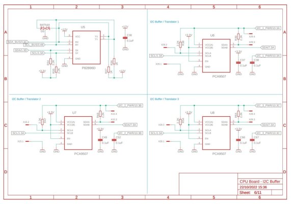
Hmm sounds like the pull up might still be the problem. 3.3V also means less current to sink to properly pull down the signal line, both through the pull-up and the lower charge on the cable capacitance.Thank you very much @Sral, I've already seen the PCA9507 datasheet and I've choosen 2.2K based on the informations right there...
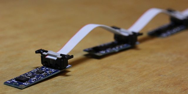
All of the devices connected before the PCA9507 works fine (DS3231, P82B96). I've now connected a Ph board to the PCA9597 with 20cm of cable and it works fine (the same thing does SHT31D with 20cm of cable).
Now I'm able to run SHT31D with long cable only attaching it directly to the 3.3V bus which sounds a bit strange, since the PCA should improve the signal quality over long distances...
I don't know what to do... maybe I can try a setup like yours, with a ISO1540 as level shifter from 3.3 to 5V and a LTC4311 to improve signal quality (which I already have but in my setup does nothing...)
What do you think?
I would therefore recommend trying a larger pull-up resistor.
how did you arrive at the 2.2k value ?