reef-pi :: An opensource reef tank controller based on Raspberry Pi.

robsworld78

Well-Known Member
View Badges
Joined
Feb 14, 2020
Messages
952
Reaction score
1,281
Location
Edmonton, Canada
Rating - 0%
0   0   0
Looks about right.

Thanks, I thought that might be the case.

If someone can give me a hand with some Arduino I2C code I have a very stable circuit that can mirror the Atlas so nothing needs to be done with Reef-pi.

This uses an ATtiny85, when I saw @Michael Lane circuit description mentioned a microcontroller I thought maybe it's the same thing?

It works like the Atlas, everything is done on board and it sends the pH value to the controller when asked. I wanted to mirror the commands that Atlas uses but was unable to as the Wire library for the ATtiny didn't support what I was trying. So I ended up doing my own thing which works fine but obviously won't work with Reef-pi which is sad because I worked so hard on this thing and now I have nothing to use it on.

I've been using it about a year on my tank and it's more stable than the Atlas. On my controller I setup a half auto calibration feature, when you put the probe in a buffer you had to wait until the reading didn't shift more than +/- 0.003 in 60 seconds, if it got to 50 seconds and the pH changed by more than the threshold the timer would start over. This circuit can do it in about 2 minutes over and over on a $70 probe, the Atlas never did it once and I tried a lot. I had to add a 5 minute timeout otherwise it would run forever trying to hit the goal.

The circuit can do temp compensation, 1, 2 or 3 point temperature compensated calibration, output the probe slopes and calibration offsets in mV so you know when to replace the probe and as a bonus the circuit is cheaper, all parts are $12.75 vs $21.62.

Downside is the ATtiny needs programming but it's easy to do and the code will be available.

I attached the Arduino sketch if anyone wants to see if they can match the I2C Atlas codes.

Reef-pi will be sending an R to get the pH so the I2C in sketch needs to respond to that and send the pH variable, should be so easy but I couldn't get it work on the ATtiny, it works on a Due when I tried with it but I couldn't put a Due on the pH circuit. So yeah this needs to be compiled for the ATtiny.

Then if Reef-pi is sending calibration values to Atlas that would need to be done as well. There's only two commands being used unless Reef-pi also sends the temperature.

For mid point Reef-pi sends - Cal,mid,7.00
For second point it sends - Cal,high,10.00

The sketch needs to respond to these incoming messages and put the 7.00 in a float and 10.00 in another float. If that's done I can tie it in. Maybe setup new variables and I'll replace with the proper one.

pH_board.jpg


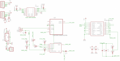
ph_schematic.png
 

Attachments

  • RoboTank_pH.zip
    3.8 KB · Views: 56
Last edited:

Matt Carden

Valuable Member
View Badges
Joined
Apr 13, 2018
Messages
1,641
Reaction score
4,084
Location
Detroit Metro
Rating - 0%
0   0   0
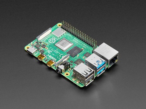
Raspberry pi 4 2gb for $35
 

Mandelstam

Well-Known Member
View Badges
Joined
Oct 29, 2017
Messages
688
Reaction score
1,117
Location
Malmö, Sweden
Rating - 0%
0   0   0
Getting closer and closer to start my reef-pi build but there are a few things I want to get sorted out first as I'm going to use it for a vivarium instead of a reef tank. Tried to do a lot of research on this but still have a few questions I want to ask the devs here.

- I'm going to have two 140mm fans inside the vivarium for airflow, think of them as the equivalent of powerheads. I want to control them via pwm and the pca9685 board as I'll be using that for the light controller too. My problem is that 4 pin pwm fans expect a 25kHz control signal and the pca9685 only outputs max 1.6kHz. To my knowledge there isn't a way to get a higher frequency from the pca9685, right?
I have two options that I see, use 2 or 3 pin fans and drive them directly with pwm over a mosfet driver. This isn't optimal for the fan motor and will likely cause it to be noisy. My other option is to basically put the whole fan controller in an arduino where I can get 25kHz pwm output and then send pwm from the reef-pi as an input to the arduino. It would only have to be a pretty basic program, read pwm --> output pwm with some delay in between.
A third option would be to use a high side mosfet driver and put a low pass filter between that and the fan so the fan receives analoge 12V dc instead of a chopped up pwm current. But if I don't want unreasonably long settling times that means it's still going to be pretty choppy with ripples.

Right now the arduino controller receiving input from the reef-pi seems to be the easiest option but I still wanted to check if you geniuses have any other ideas to check out.
 

robsworld78

Well-Known Member
View Badges
Joined
Feb 14, 2020
Messages
952
Reaction score
1,281
Location
Edmonton, Canada
Rating - 0%
0   0   0
Getting closer and closer to start my reef-pi build but there are a few things I want to get sorted out first as I'm going to use it for a vivarium instead of a reef tank. Tried to do a lot of research on this but still have a few questions I want to ask the devs here.

- I'm going to have two 140mm fans inside the vivarium for airflow, think of them as the equivalent of powerheads. I want to control them via pwm and the pca9685 board as I'll be using that for the light controller too. My problem is that 4 pin pwm fans expect a 25kHz control signal and the pca9685 only outputs max 1.6kHz. To my knowledge there isn't a way to get a higher frequency from the pca9685, right?
I have two options that I see, use 2 or 3 pin fans and drive them directly with pwm over a mosfet driver. This isn't optimal for the fan motor and will likely cause it to be noisy. My other option is to basically put the whole fan controller in an arduino where I can get 25kHz pwm output and then send pwm from the reef-pi as an input to the arduino. It would only have to be a pretty basic program, read pwm --> output pwm with some delay in between.
A third option would be to use a high side mosfet driver and put a low pass filter between that and the fan so the fan receives analoge 12V dc instead of a chopped up pwm current. But if I don't want unreasonably long settling times that means it's still going to be pretty choppy with ripples.

Right now the arduino controller receiving input from the reef-pi seems to be the easiest option but I still wanted to check if you geniuses have any other ideas to check out.

How about something like this fan, it's 5-12v so you could drive a mosfet with PWM and use the PWM value that allows the mosfet to output 5v as the minimum value and adjust up from there.


Something like this mosfet should get you down to 5v.

https://www.adafruit.com/product/355
 

AbjectMaelstroM

Valuable Member
View Badges
Joined
Jul 21, 2019
Messages
1,527
Reaction score
1,810
Location
RVA
Rating - 100%
1   0   0
Raspberry pi 4 2gb for $35

Time to upgrade the Pi 3B. Gonna wait for Amazon pricing to catch up to shave off shipping.
 
Last edited:

Alaa

Community Member
View Badges
Joined
Nov 28, 2018
Messages
74
Reaction score
80
Rating - 0%
0   0   0
Getting closer and closer to start my reef-pi build but there are a few things I want to get sorted out first as I'm going to use it for a vivarium instead of a reef tank. Tried to do a lot of research on this but still have a few questions I want to ask the devs here.

- I'm going to have two 140mm fans inside the vivarium for airflow, think of them as the equivalent of powerheads. I want to control them via pwm and the pca9685 board as I'll be using that for the light controller too. My problem is that 4 pin pwm fans expect a 25kHz control signal and the pca9685 only outputs max 1.6kHz. To my knowledge there isn't a way to get a higher frequency from the pca9685, right?
I have two options that I see, use 2 or 3 pin fans and drive them directly with pwm over a mosfet driver. This isn't optimal for the fan motor and will likely cause it to be noisy. My other option is to basically put the whole fan controller in an arduino where I can get 25kHz pwm output and then send pwm from the reef-pi as an input to the arduino. It would only have to be a pretty basic program, read pwm --> output pwm with some delay in between.
A third option would be to use a high side mosfet driver and put a low pass filter between that and the fan so the fan receives analoge 12V dc instead of a chopped up pwm current. But if I don't want unreasonably long settling times that means it's still going to be pretty choppy with ripples.

Right now the arduino controller receiving input from the reef-pi seems to be the easiest option but I still wanted to check if you geniuses have any other ideas to check out.
Hi
I'm using ARCTIC F12 PWM PST and Noctua NF-A6x25 PWM controlled directly by pca9685 with no issues, just connect the ground of the pca to the fan ground and use any pin to control the fan PWM. use the appropriate power supply for the fan
 

Mandelstam

Well-Known Member
View Badges
Joined
Oct 29, 2017
Messages
688
Reaction score
1,117
Location
Malmö, Sweden
Rating - 0%
0   0   0
Hi
I'm using ARCTIC F12 PWM PST and Noctua NF-A6x25 PWM controlled directly by pca9685 with no issues, just connect the ground of the pca to the fan ground and use any pin to control the fan PWM. use the appropriate power supply for the fan

That sounds like good news! As I don't have all the parts yet I haven't done any real trials. What frequency are you getting from the pca9685? No weird noises/whining/clicking?
 

Alaa

Community Member
View Badges
Joined
Nov 28, 2018
Messages
74
Reaction score
80
Rating - 0%
0   0   0
That sounds like good news! As I don't have all the parts yet I haven't done any real trials. What frequency are you getting from the pca9685? No weird noises/whining/clicking?
i'm using the default frequency maybe 800 and it is working for the fans and doser (connected through Dual Large Power MOS Transistor Driving Module)
the Noctua is somewhat noisy when the power goes above 50% (used to cool the pi case), the arctic f12 is quieter
you can try different frequencies and see how it goes
 

Mandelstam

Well-Known Member
View Badges
Joined
Oct 29, 2017
Messages
688
Reaction score
1,117
Location
Malmö, Sweden
Rating - 0%
0   0   0
i'm using the default frequency maybe 800 and it is working for the fans and doser (connected through Dual Large Power MOS Transistor Driving Module)
the Noctua is somewhat noisy when the power goes above 50% (used to cool the pi case), the arctic f12 is quieter
you can try different frequencies and see how it goes

I'll do some testing before going down another route. I'm mostly worried about added noise due to the fact that the fans will be running 24/7 at different speeds. The industry standard for the signal pwm is 25kHz +-3k mostly because it pushes the signal above the audible range.
 
OP
OP
Ranjib

Ranjib

7500 Club Member
View Badges
Joined
Apr 16, 2016
Messages
9,843
Reaction score
17,056
Location
Pleasant Hill, Concord
Rating - 0%
0   0   0
Thanks, it does look complicated, that's what scared from the Pi. At some point I'm still going to give it a shot, gotta learn somehow.

On a different note, I just hooked up one of these pH circuits, it works and I get -8036 which sounds ok based on what I've read but how do I get it to show an actual pH value?

https://github.com/reef-pi/pH-Board
Calibrate.
 

AbjectMaelstroM

Valuable Member
View Badges
Joined
Jul 21, 2019
Messages
1,527
Reaction score
1,810
Location
RVA
Rating - 100%
1   0   0

Michael Lane

Well-Known Member
View Badges
Joined
Aug 11, 2018
Messages
677
Reaction score
1,123
Rating - 0%
0   0   0
Is there a way a person can setup Reef-pi for easy editing basically like an Arduino, as in make a small change, upload and view? I mostly use Visual Studio Code on windows. I'm dying to see what makes it tick and to know if I have any chance of contributing to it. As a challenge these are the two things I would like to see if I could pull off.

The first it appears a dosing pump can only be activated with a schedule and calibration, it would be nice to trigger one at any given time using a macro. Looks like they are only enabled/disabled via the macro.

The other is with the equipment tab, thinking an option when you add a piece of equipment to select AC or DC, if DC is selected you can set a min/max speed. I see this useful for pumps, fans, lights etc. that you might only want to run based on sensor feedback and need to change the speed. Its fine now but everything runs at 100%.
As Ranjib said, reef-pi is quite a bit different from arduino, but you can actually run it on Windows depending on what features you are interested in testing.

I typically use VS Code on Windows for reef-pi development. Obviously, I can't interact with gpio or i2c, but we have mock drivers in dev mode that provide some insight into what would happen on actual hardware.

It's easy to cross compile with go, so you can build your changes and copy them to the rpi and try it out on the actual hardware. The cycle isn't quite as quick as arduino, but it's possible.
 

Michael Lane

Well-Known Member
View Badges
Joined
Aug 11, 2018
Messages
677
Reaction score
1,123
Rating - 0%
0   0   0
How stable of readings should one expect with this pH circuit?

https://github.com/reef-pi/pH-Board

I'm getting a range from 8.11 to 8.18, almost every reading the 100th is different by 3-4 points.

@Michael Lane is your circuit different? I noticed in the description it said it has a microcontroller but on the schematic I see the same components as the link above.

My ph board is different from robertoB's original design. The isolation chip (ADM3260) was getting a bit more difficult to source, so I worked up a new design. It is compatible with the ph-board driver, but it does use a microcontroller to read the ADC.

Even though the boards are isolated, it's still possible to see interference from anything radiating noise. I'm not sure that's what you are seeing, but it could be. robertoB's design is basically direct access to an ADC and the ph-board driver doesn't implement any smoothing or noise rejection.
 

Michael Lane

Well-Known Member
View Badges
Joined
Aug 11, 2018
Messages
677
Reaction score
1,123
Rating - 0%
0   0   0
I'll do some testing before going down another route. I'm mostly worried about added noise due to the fact that the fans will be running 24/7 at different speeds. The industry standard for the signal pwm is 25kHz +-3k mostly because it pushes the signal above the audible range.
Is there a typical module for 25kHz pwm from adafruit or sparkfun? reef-pi 3 reworked the way drivers are implemented, so it might be reasonable to add some new hardware support.
 

Mandelstam

Well-Known Member
View Badges
Joined
Oct 29, 2017
Messages
688
Reaction score
1,117
Location
Malmö, Sweden
Rating - 0%
0   0   0
Is there a typical module for 25kHz pwm from adafruit or sparkfun? reef-pi 3 reworked the way drivers are implemented, so it might be reasonable to add some new hardware support.

I'm not sure if there is. I've seen a couple of other pwm boards on Adafruit but couldn't find any details on frequency in the specs. I've never used the PCA9685 board before but is there a way to lower the resolution and push up the frequency that way?
I was actually a bit surprised by the lack of options there are for fan control when it comes to hardware. Maybe it's because its mainly done via a motherboard of a pc.

It would be nice to have some hardware support for pwm fan control if there is a suitable board for it. Variable fan speed might not be critical for a reef but it could make for better chiller options and control. Bigger fans on lower rpms means less noise but with the possibility to kick it up when the need is greater.
 
Back
Top