reef-pi :: An opensource reef tank controller based on Raspberry Pi.

AbjectMaelstroM

Valuable Member
View Badges
Joined
Jul 21, 2019
Messages
1,527
Reaction score
1,811
Location
RVA
Rating - 100%
1   0   0
TDS. They are a rural provider. I had my security cameras setup to send images to my email at one point, but for some reason they thought I was sending spam and blocked all outbound SMTP. Even through their own servers... Told me I needed to call tech support to get it fixed. I've not done it yet because I've been too busy and I hate sitting on hold.....

Dang, that sucks.
 

Des Westcott

Well-Known Member
View Badges
Joined
May 29, 2018
Messages
646
Reaction score
1,035
Location
Durban - South Africa
Rating - 0%
0   0   0
Update on the ATO usage issue. I have been running the ATO on the old settings to with an alert if usage goes over 600 seconds and "disable on alert" enabled. ATO has been running as expected and usage has been below 600 (as expected).

Suddenly now at 13H00 I get a flurry of mails come through that the usage is high (1350 seconds) and when I look, ATO has been disabled despite having a usage of 0 seconds for the current hour. Previous hour was 130 seconds according to the graph. I've looked and in the 1 month history on the graph, I can't find an hour that actually has 1350 seconds usage.

2020-04-09.png


Not sure of reason, just reporting symptom.
 

robsworld78

Well-Known Member
View Badges
Joined
Feb 14, 2020
Messages
952
Reaction score
1,281
Location
Edmonton, Canada
Rating - 0%
0   0   0
Hi all.

Waiting for RoboTank controller, I'm playing with my Raspberry and Reef-pi.

I'm not able to setup email alerts.

Every time I try to configure it (from hotmail to hotmail or gmail email address; from gmail to gmail or hotmail email address), I click on the "update" and then to the "Send a message" bottons. Often nothing happens or.... sometimes I receive an error message.

For hotmail I wrote smtp.live.com and port 25 or 465;
For gmail I wrote smtp.gmail.com and port 587, 25 or 465

Of course I have checked in the spam folder.... nothing!!!

If I go to the admin tag and I restart the service and/or reboot the system, when I come back in the telemetry tag... there is no password!!!

Any helps?

I just tried a Google account and it didn't work without changing some security settings. Try this.

Step 1. Go to https://www.google.com and follow directions on image.

gmail_step1.jpg


Step 2. Click the 'Security' link on left side menu

gmail_step2.jpg


Step 3. Near the top you will see the 'Signing in to Google' section, turn off '2-Step Verification'.

gmail_step3.jpg


Step 4. Now scroll down to the bottom of the page, you will see the 'Less secure app access' section. This will mostly like be turned off, turn it on.

gmail_step4.jpg


Step 5. In Reef-pi go to the 'Configuration' tab at the top and go to the 'Telemetry' sub-tab. Make sure 'Email alerts' check box is checked and fill out the fields below.
  • server - This is the SMTP address for your email server, the default value is for Gmail so you can leave it as is.
  • port - This is the port number for your email server, Gmail uses 587.
  • from - This is the email address the alert is sent from. Enter the same address from Step 1.
  • To - This is the email address the alert is sent to, any address will work.
  • Password - This is the password to access your Gmail account, use the same 'password' that you used to log into your Gmail account. (Note: When you view this page later the password field will be blank for your security)
  • limit per hour - this is the maximum number of emails Reef-pi will send per hour, the default value of 10 is good for most setups.
Step 6. Once you have added your credentials click the 'Update' button.

Note: Do not click the 'Send test message' button until you have finished Step 7

gmail_step5.jpg


Step 7. From the 'configuration' tab click the 'Admin' sub-tab link. Click 'Reload' to restart Reef-pi so the changes you made will take effect.

Now you can return back to the 'Telemetry' sub-tab and press the 'Send test message' to verify it works.

gmail_step6.jpg
 

Freccialata

Community Member
View Badges
Joined
Jan 31, 2020
Messages
53
Reaction score
98
Location
Rome (Italy)
Rating - 0%
0   0   0
I solved the problem:
1) 2 steps verifications;
2) password for app;

It still didn't work, so I did the third point:

3) reset of the reef-pi database;
4) after that I set again email alerts... now it works like a charm;
5) added again HS110 smart plug;
6) added again temperature sensor.

Everything is fine.

Thank you everyone for help.
 

bishoptf

Valuable Member
View Badges
Joined
Jan 1, 2019
Messages
1,344
Reaction score
1,722
Location
Missouri
Rating - 0%
0   0   0
Looking for some suggestions from @Michael Lane or whoever may be able to help me test my ML Goby Hat. I have 5v and 12v wired up but I am unable to get all of the relays working on the hat. I verified with my working pi unit that the DJ power strip is working properly, I have tried 2 pi zero's but I am getting the same issue, only io22 will trip the relay, all the others are nada except for an odd one, if I turn on io10 and io24 both to on it will trip a relay and if you turn them both off it turns it off, however if you do them one at a time nothing.


Here are my connector to IO ports:
io25
io9
io8
io11
io10
io24
io23
io22

Using one of the ribbon cable to serial connectors for the cable, if anyone has any suggestions on how to pinpoint the issue with a meter etc would be appreciated.

Thanks!
:)
 

drbogger

Active Member
View Badges
Joined
Apr 24, 2019
Messages
165
Reaction score
132
Location
Ballston Spa, New York
Rating - 0%
0   0   0
Looking for some suggestions from @Michael Lane or whoever may be able to help me test my ML Goby Hat. I have 5v and 12v wired up but I am unable to get all of the relays working on the hat. I verified with my working pi unit that the DJ power strip is working properly, I have tried 2 pi zero's but I am getting the same issue, only io22 will trip the relay, all the others are nada except for an odd one, if I turn on io10 and io24 both to on it will trip a relay and if you turn them both off it turns it off, however if you do them one at a time nothing.


Here are my connector to IO ports:
io25
io9
io8
io11
io10
io24
io23
io22

Using one of the ribbon cable to serial connectors for the cable, if anyone has any suggestions on how to pinpoint the issue with a meter etc would be appreciated.

Thanks!
:)

First, I would eliminate the ribbon cable as being faulty... Try a different cable, or test the cable using a continuity meter.

Then, I would test the actual relays to be sure they are not faulty.

If those all check out, then I would troubleshoot the pi hat.

I've been trying to work out issues of my own as well, and I'm not having too much luck yet.
 

bishoptf

Valuable Member
View Badges
Joined
Jan 1, 2019
Messages
1,344
Reaction score
1,722
Location
Missouri
Rating - 0%
0   0   0
First, I would eliminate the ribbon cable as being faulty... Try a different cable, or test the cable using a continuity meter.

Then, I would test the actual relays to be sure they are not faulty.

If those all check out, then I would troubleshoot the pi hat.

I've been trying to work out issues of my own as well, and I'm not having too much luck yet.

Yeah i've tried several things, I tried the DJ strip on my existing working reefpi and all the relays are working, i tried hooking up a serial breakout and verified i am getting 12v to the pins but not I can't get any of them to work. Right now I have V+ plug in to port 5 and one wire going to pin1 which should be io22 and I get nothing. Maybe I fried the ULN2803A, ugh my soldering skills are junk and trying to re-solder that SMD will be laughable. I'm not sure what else to test to isolate the issue.
 

GaryE

Well-Known Member
View Badges
Joined
Mar 12, 2020
Messages
992
Reaction score
1,384
Location
Coatesville, Indiana
Rating - 0%
0   0   0
I have a potentially dumb question about the instructions for build.
Yeah i've tried several things, I tried the DJ strip on my existing working reefpi and all the relays are working, i tried hooking up a serial breakout and verified i am getting 12v to the pins but not I can't get any of them to work. Right now I have V+ plug in to port 5 and one wire going to pin1 which should be io22 and I get nothing. Maybe I fried the ULN2803A, ugh my soldering skills are junk and trying to re-solder that SMD will be laughable. I'm not sure what else to test to isolate the issue.

can you post close up pics of the device? perhaps a magnified pic of your solder joints?

I had a similar issue and it was just a solder joint that was bridging to ground that needed high magnification to see.
 

AbjectMaelstroM

Valuable Member
View Badges
Joined
Jul 21, 2019
Messages
1,527
Reaction score
1,811
Location
RVA
Rating - 100%
1   0   0
Yeah i've tried several things, I tried the DJ strip on my existing working reefpi and all the relays are working, i tried hooking up a serial breakout and verified i am getting 12v to the pins but not I can't get any of them to work. Right now I have V+ plug in to port 5 and one wire going to pin1 which should be io22 and I get nothing. Maybe I fried the ULN2803A, ugh my soldering skills are junk and trying to re-solder that SMD will be laughable. I'm not sure what else to test to isolate the issue.

Try v+ and io23 let me know if it works.
 

bishoptf

Valuable Member
View Badges
Joined
Jan 1, 2019
Messages
1,344
Reaction score
1,722
Location
Missouri
Rating - 0%
0   0   0
Try v+ and io23 let me know if it works.

Yeah nothing, I am looking at the schematic and I see the layout, if I check voltage across the pins on my serial connection I get 12v on each pin except for pin1. Right now I only have v+ hooked up and trying individual pins to see if I can get anything to work, now I cannot get any io ports to work.
 

bishoptf

Valuable Member
View Badges
Joined
Jan 1, 2019
Messages
1,344
Reaction score
1,722
Location
Missouri
Rating - 0%
0   0   0
Yeah nothing, I am looking at the schematic and I see the layout, if I check voltage across the pins on my serial connection I get 12v on each pin except for pin1. Right now I only have v+ hooked up and trying individual pins to see if I can get anything to work, now I cannot get any io ports to work.

Replying to myself, I think I have it sorted although I am still scratching my head, I had Mike's pin out and I need to verify. Has anyone used one of the ribbon cables, I tried several and couldn't get them to work, I had a a screw terminal type and with jumper cables figured it out, was wanting to go with the ribbon cable type to take up less room but not sure what is not correct or what I may be doing wrong. When I take v+ to pin 5 they all appear to work.

UPDATE: Looking at one of Mike's hat pics which I guessed I missed, duh, these are the correct mappings, still not sure why they won't work with my ribbon cable, will purchase an additional one to try out.

Here are the mapping that I am getting with my pi zero

8 11
25 9
24 10
22 23
v+

Hopefully someone will tell me how I messed things up but I am glad that it doesnt appear that the uln2803 is fried, all appeared to be working.

On a separate subject I need to figure out an ATO solution, what tends to be the most reliable?

Thanks!
:)
 
Last edited:

AbjectMaelstroM

Valuable Member
View Badges
Joined
Jul 21, 2019
Messages
1,527
Reaction score
1,811
Location
RVA
Rating - 100%
1   0   0
On a separate subject I need to figure out an ATO solution, what tends to be the most reliable?

Thanks!
:)

Reliable as far as what? Sensors? Pump?

Simple tends to be reliable with caviats. For sensors float switch or optical (optical will require a resistor)... Both would need to be checked to make sure there's no crud built up from time to time. Pump? Personal preference... I bought a Tunze osmolator replacement pump for $20 and it has served me well for about 4-5 months now.

You can also use no contact sensors like externally mounted ultrasonic sensors, but they're not super sensitive/accurate with detecting level. I probably wouldn't use one to check tank water level but I'm using one on my ATO container to check when it needs a refill; works great for that.
 

bishoptf

Valuable Member
View Badges
Joined
Jan 1, 2019
Messages
1,344
Reaction score
1,722
Location
Missouri
Rating - 0%
0   0   0
Reliable as far as what? Sensors? Pump?

Simple tends to be reliable with caviats. For sensors float switch or optical (optical will require a resistor)... Both would need to be checked to make sure there's no crud built up from time to time. Pump? Personal preference... I bought a Tunze osmolator replacement pump for $20 and it has served me well for about 4-5 months now.

You can also use no contact sensors like externally mounted ultrasonic sensors, but they're not super sensitive/accurate with detecting level. I probably wouldn't use one to check tank water level but I'm using one on my ATO container to check when it needs a refill; works great for that.

Thanks, I just not sure where to start, ML hat has 2 ato ports on it and trying to figure out parts that I need to build an ATO. I want something that for top off and I think I would like a high level switch to notify me if my pump fails, since it drains back into the sump I could use the high level device to notify me of that event. Seems like most are running dual floats to turn off the pump if the switch gets stuck, if I use both floats for that I will need to think of something else that will notify me if my return pump fails.

So much to learn and figure out, I have my DT plumbed to my sump but need powerheads, return pump, lights and more. :)
 

bishoptf

Valuable Member
View Badges
Joined
Jan 1, 2019
Messages
1,344
Reaction score
1,722
Location
Missouri
Rating - 0%
0   0   0
Well I figured out the ribbon cable, helps to send the #9 pin (v+) to #5 on the connector end, once you do that it all works, such a Doh! moment. Sorry to clutter up the forum for real issues, now to go figure out what to do about ATO and all my other pressing issues.

@Michael Lane I am looking at the Mars aqua for lighting, I know I saw some posts that detailed the connector piece in the lights but unable to find it. If you have that handy I would appreciate it, I think you also used mini xlr connectors for the light portion also, is that correct?

Hope everyone is staying safe and doing well!
:)

I think I need to go start my build thread, here is close to a latest picture, I have the back painted black now but close to where I am at the moment.
IMG_20200403_164122.jpg
 
Last edited:

Bliff

New Member
View Badges
Joined
Apr 6, 2020
Messages
18
Reaction score
41
Rating - 0%
0   0   0
That's a nice sump. And the plumbing work looks A+ as well :)

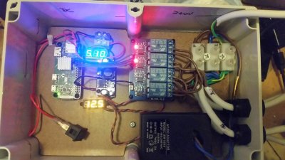
Anyhow. Thanks to the devs and all the folks that have put together this awesome system. I've built my reef-pi and so far, it's been quite an approachable project.
I went with a LM2596 DC-DC buck converter and used a 12V 2.1A wall wart as the main power supply.
Those LED voltage meters are entirely superfluous, and I had them because they were impulse $1 buys from Aliexpress and looked nifty, so I had a few sitting around. I left them in for bling reasons.

Things Learned
If I were doing this from scratch, I'd consider using an external pack and adding a 12V input socket, since this is an IP68 enclosure, so things might get a lttle warm inside. It does seem to radiate some heat via the side wall though. I've considered using a small internal fan, just to circulate more air inside the case and therefore help to convect heat out through the other walls.

If you let your 6yo see the reef-pi control panel on their tablet, they will test how quickly all your relays can cycle (quite quickly, I found).

To Do
I have set up a PWM controlled LED, and it all worked as it should. That's not in this box though. What I'd like to make is a PWM controlled LED light batten entirley from DIY. I have some 10W, 12V LED modules. As I understand it, I would be using a power MOSFET with logic level gate driven directly from the PWM pin (does that need an RP protection diode?). I read in the light controller guide that some folks are making exactly that, but this is a very long thread and I haven't seen anything about that so far.
Is there another thread out there with this discussion? I'm a little stuck for search keywords.

Also, is there a specific thread/bug tracker for feature requests/suggestions? Is that this thread?

20200403_213620.jpg
 

Bliff

New Member
View Badges
Joined
Apr 6, 2020
Messages
18
Reaction score
41
Rating - 0%
0   0   0
E: Ctrl-Enter is POSTNOWDOIT

Oh and ALSO, I note that the guide recommends 3.5mm audio jacks as a connector, but the problem with those particularly on the temperature controller is that they momentarily make a ground connection during plugging, which restarts the pi. Instead, I had some of these sitting around:
hU7gnU9m.jpg

They aren't exactly panel mountable, but with a tight fitting cable gland you have a watertight connection for up to 5 pins.
I figure this might be of use to some folks.


Also, there's plenty of other kinds as well and they seem suited to panel mounting.
Example: https://www.aliexpress.com/item/32812653428.html
 
Last edited:

bishoptf

Valuable Member
View Badges
Joined
Jan 1, 2019
Messages
1,344
Reaction score
1,722
Location
Missouri
Rating - 0%
0   0   0
Anyhow. Thanks to the devs and all the folks that have put together this awesome system. I've built my reef-pi and so far, it's been quite an approachable project.
I went with a LM2596 DC-DC buck converter and used a 12V 2.1A wall wart as the main power supply.
Those LED voltage meters are entirely superfluous, and I had them because they were impulse $1 buys from Aliexpress and looked nifty, so I had a few sitting around. I left them in for bling reasons.

Things Learned
If I were doing this from scratch, I'd consider using an external pack and adding a 12V input socket, since this is an IP68 enclosure, so things might get a lttle warm inside. It does seem to radiate some heat via the side wall though. I've considered using a small internal fan, just to circulate more air inside the case and therefore help to convect heat out through the other walls.

If you let your 6yo see the reef-pi control panel on their tablet, they will test how quickly all your relays can cycle (quite quickly, I found).

To Do
I have set up a PWM controlled LED, and it all worked as it should. That's not in this box though. What I'd like to make is a PWM controlled LED light batten entirley from DIY. I have some 10W, 12V LED modules. As I understand it, I would be using a power MOSFET with logic level gate driven directly from the PWM pin (does that need an RP protection diode?). I read in the light controller guide that some folks are making exactly that, but this is a very long thread and I haven't seen anything about that so far.
Is there another thread out there with this discussion? I'm a little stuck for search keywords.

Also, is there a specific thread/bug tracker for feature requests/suggestions? Is that this thread?

20200403_213620.jpg


Looks good, Welcome to R2R...looks like a good start!

:)
 

crusso1993

7500 Club Member
View Badges
Joined
Oct 21, 2018
Messages
8,671
Reaction score
44,648
Location
SW, FL, USA
Rating - 0%
0   0   0
Anyhow. Thanks to the devs and all the folks that have put together this awesome system. I've built my reef-pi and so far, it's been quite an approachable project.
I went with a LM2596 DC-DC buck converter and used a 12V 2.1A wall wart as the main power supply.
Those LED voltage meters are entirely superfluous, and I had them because they were impulse $1 buys from Aliexpress and looked nifty, so I had a few sitting around. I left them in for bling reasons.

Things Learned
If I were doing this from scratch, I'd consider using an external pack and adding a 12V input socket, since this is an IP68 enclosure, so things might get a lttle warm inside. It does seem to radiate some heat via the side wall though. I've considered using a small internal fan, just to circulate more air inside the case and therefore help to convect heat out through the other walls.

If you let your 6yo see the reef-pi control panel on their tablet, they will test how quickly all your relays can cycle (quite quickly, I found).

To Do
I have set up a PWM controlled LED, and it all worked as it should. That's not in this box though. What I'd like to make is a PWM controlled LED light batten entirley from DIY. I have some 10W, 12V LED modules. As I understand it, I would be using a power MOSFET with logic level gate driven directly from the PWM pin (does that need an RP protection diode?). I read in the light controller guide that some folks are making exactly that, but this is a very long thread and I haven't seen anything about that so far.
Is there another thread out there with this discussion? I'm a little stuck for search keywords.

Also, is there a specific thread/bug tracker for feature requests/suggestions? Is that this thread?

20200403_213620.jpg

Welcome to R2R and using a reef pi! Your setup looks pretty nice.

As far as bugs are concerned, people often post bugs they encounter in this thread. However, it is recommended to start and maintain your own reef pi build thread in the DYI forum.

Regarding feature/UI development suggestions please see the link below.


Dave's Reef

Active Member
View Badges
Joined
Nov 4, 2018
Messages
102
Reaction score
150
Rating - 0%
0   0   0
Has anyone had any issues with running more than two temp probes? I wanted to run 5 of them but seems to cause issues they keep faulting or not connecting at all? Is there a limit to the length? I would say my longest one is about 20' away. i had the same issue with my older pie also and just went down to running two but with my new build I have added a frag tank and also a mixing station temp as well as house temp.
 

High pressure shells: Do you look for signs of stress in the invertebrates in your reef tank?

  • I regularly look for signs of invertebrate stress in my reef tank.

    Votes: 41 32.0%
  • I occasionally look for signs of invertebrate stress in my reef tank.

    Votes: 29 22.7%
  • I rarely look for signs of invertebrate stress in my reef tank.

    Votes: 25 19.5%
  • I never look for signs of invertebrate stress in my reef tank.

    Votes: 33 25.8%
  • Other.

    Votes: 0 0.0%
Back
Top