reef-pi :: An opensource reef tank controller based on Raspberry Pi.

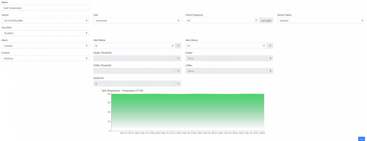
Hey all, I recently upgraded to 5.1 and now I can't seem to change my ranges or colors of my graphs, does anyone know where it went? Screenshot showing where it used to be but now I don't see the option to change color or range.
1645068914120.png
Just as an update, I opened in Chrome and the settings are there, so there's some issue with either my particular setup in Firefox or Firefox in general
 
Just as an update, I opened in Chrome and the settings are there, so there's some issue with either my particular setup in Firefox or Firefox in general
After every update to reefpi, close all reef-pi tabs, and when you open a new one hit control+F5, that should clear out most remnants that firefox has kept from old versions
 
I have the zero w ( don't know what version), and want to enable remote access with vnc (so I can access it over the internet from anywhere). The one I have is not fast enough to do this. Which rpi is recommended for this?
I went down a long rabbit hole trying to figure this out. Tailscale is the only way to do this. And it works reliably. I will send you a link in a moment.
 
I have the zero w ( don't know what version), and want to enable remote access with vnc (so I can access it over the internet from anywhere). The one I have is not fast enough to do this. Which rpi is recommended for this?
Tailscale. This dude posted this link that solved this problem for me. Been using it for months so far and can reach the web ui from anywhere without issue. You set up an account. Run some basic commands on the pi,, then install tailscale on your phone/pc and you can access it from anywhere just like you are at home. https://www.reef2reef.com/threads/reef-pi-5-0-release-announcement.874824/post-9788797
 
Eh I trust no one, they are still in the middle and setting things up for the wireguard tunnels underneath. It's probably better than a lot of the other stuff out there like port forwarding etc...

Nebula FTW :)
 
@Michael Lane boards that I had JLCPCB make came in today, they look really good. Wish they had the pca9685 in stock since I somehow have to attempt to not botch them when adding it to the board, lol :)

PXL_20220221_190053492.jpg

They do good work.. PCA9685 isn't too bad. Just don't go crazy with the solder..

Try doing a sht31 sometime.. 8 pins and it's the size of an 805 resistor... but square. Very difficult to solder.

I have a few of this board on the way. (but in black) I even included a couple Adafruit Stemma QT connectors for use with their ready made sensor boards. Just for kicks.

I didn't have them solder anything, I'll do all of that myself, but I did have them make me a stencil to make it a bit easier.

1645471105749.png
 
Well here we go, second board, not nearly as clean as @Michael Lane, his boards were unbelievable clean. I think he ultrasonically clean the boards when he was finished, not a bit of flux anywhere. His board is on the left and the ones I just made up is on the right...

PXL_20220223_025005606.jpg


PXL_20220223_024352588.jpg


Here is what I ended up with to get close up, highly recommended since it really gives you room to work and your not right up against the board, about 8" of work room and better than the other devices I tried, called a solder scope - https://www.qsl.net/k9ac/solderScope.html

PXL_20220223_024820732.jpg


Hardest part is mounting the eyeglass lenses, not a fan of the tape and cardboard, wanted to come up with something I could 3d print but rolling with this for now, lets you see everything comfortable and really clear. One question that one of you smart guys can answer, it has some pca9685 spots on the board that I think are for testing the chip out but can anyone enlighten me how I can do that, since I soldered the pca9685 looks good to me but is there an easy way to test it with those pads?

Thanks for all the tips and tricks...:)

 
They do good work.. PCA9685 isn't too bad. Just don't go crazy with the solder..

Try doing a sht31 sometime.. 8 pins and it's the size of an 805 resistor... but square. Very difficult to solder.

I have a few of this board on the way. (but in black) I even included a couple Adafruit Stemma QT connectors for use with their ready made sensor boards. Just for kicks.

I didn't have them solder anything, I'll do all of that myself, but I did have them make me a stencil to make it a bit easier.

1645471105749.png
Are you going to be selling these?
 
Well here we go, second board, not nearly as clean as @Michael Lane, his boards were unbelievable clean. I think he ultrasonically clean the boards when he was finished, not a bit of flux anywhere. His board is on the left and the ones I just made up is on the right...

PXL_20220223_025005606.jpg


PXL_20220223_024352588.jpg


Here is what I ended up with to get close up, highly recommended since it really gives you room to work and your not right up against the board, about 8" of work room and better than the other devices I tried, called a solder scope - https://www.qsl.net/k9ac/solderScope.html

PXL_20220223_024820732.jpg


Hardest part is mounting the eyeglass lenses, not a fan of the tape and cardboard, wanted to come up with something I could 3d print but rolling with this for now, lets you see everything comfortable and really clear. One question that one of you smart guys can answer, it has some pca9685 spots on the board that I think are for testing the chip out but can anyone enlighten me how I can do that, since I soldered the pca9685 looks good to me but is there an easy way to test it with those pads?

Thanks for all the tips and tricks...:)

Looks awesome
 
Well here we go, second board, not nearly as clean as @Michael Lane, his boards were unbelievable clean. I think he ultrasonically clean the boards when he was finished, not a bit of flux anywhere. His board is on the left and the ones I just made up is on the right...

PXL_20220223_025005606.jpg


PXL_20220223_024352588.jpg


Here is what I ended up with to get close up, highly recommended since it really gives you room to work and your not right up against the board, about 8" of work room and better than the other devices I tried, called a solder scope - https://www.qsl.net/k9ac/solderScope.html

PXL_20220223_024820732.jpg


Hardest part is mounting the eyeglass lenses, not a fan of the tape and cardboard, wanted to come up with something I could 3d print but rolling with this for now, lets you see everything comfortable and really clear. One question that one of you smart guys can answer, it has some pca9685 spots on the board that I think are for testing the chip out but can anyone enlighten me how I can do that, since I soldered the pca9685 looks good to me but is there an easy way to test it with those pads?

Thanks for all the tips and tricks...:)
Nice job, I knew you could do it. :) @Michael Lane did have very clean boards, he posted a close up of one, I couldn't believe how clean it was, he said he used an ultrasonic cleaner and some manually scrubbing. Based on how much detail he put in them I can tell you he wasn't in it for the money. Those pads are to change the I2C address for the pca9685, there's 64 combinations allowing 64 pca9685 or 1024 outputs. :eek: You can test with volt meter or better with an oscilloscope.

 
I'm gonna ask before I start putting this together. Is the guide updated on the website? Is there any extra options? Anything like that? Sorry for asking, but this thread is 907 pages long
 
I'm gonna ask before I start putting this together. Is the guide updated on the website? Is there any extra options? Anything like that? Sorry for asking, but this thread is 907 pages long
So many ways to go about it... the basic guide on github.. still stands .. but could use an update or two.. if you are not a tech and a hack like me robo-tank is good to look at.

Bigger question is what is it you want it do do?
 
Last edited:
Man there is not a rpi to be found anywhere, crazy times....
:-( sme here. I have two that I need to replace, they went down after serving for almost 5 years. I have dozens of empty enclosure waiting . even before all this adafruit used to restrict one piece every shipping.
 
:-( sme here. I have two that I need to replace, they went down after serving for almost 5 years. I have dozens of empty enclosure waiting . even before all this adafruit used to restrict one piece every shipping.
Yeah, man it's pretty crazy with things out there, even the old ones going over $50 on ebay, no idea when things will get back in any semblance of normal. I have a bead on someone that has some zero w's, if I can get them for a decent price I will let you know if your interested.
 

TOP 10 Trending Threads

ARE YOU READY TO CONFESS TO CRAZIEST, DUMBEST, FUNNIEST THING YOU’VE EVER DONE IN REEFING?

  • Yeah, I'll confess! (Share your story in the comments!)

    Votes: 19 59.4%
  • Nah, I'll keep mine a secret...(Don't be like that, share with the class!)

    Votes: 13 40.6%
Back
Top
Home
Post thread…
Market
What's new









