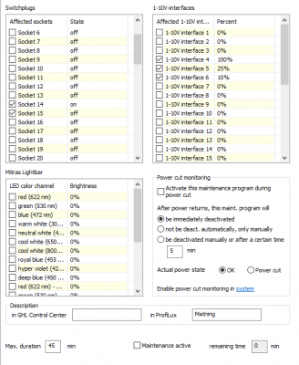
Use of 1-10 V devices is more or less standard today. This include LED fixtures, return pumps and wavemakers. Already from the beginning there is very good functions in order to control illumination with the 32 separately 1-10 V functions (L1-L32) in the software and P4 comes with 6 separate hardware channels. However - the control of L1 to L32 can be dynamically done only by illumination channels, stream groups, maintenance programs and flowmeters. For the moment you can´t use programmable logic in order to let - as an example - a skimmer to rise its pumpfrequensy if pH drop (or rise to much) in order to adjust the gas exchange in the skimmer or to lower the return pumps speed when feeding. If you want this - you need to do it with the maintenance or feed programming - but as it is for the moment - you have to activate maintenance and feed mode manually by MyGHL, Profilux touch or GCC. At least what I have discover - if I have miss something - please let me know. When I feed my fishes today - I want my return and skimmer pump to drop to around 10 % speed in order to prolong the time the food will be in the DT. I feed with much of small food like frozen artemia, mysis and copepods. I have a maintenance program that fix that for me and I start it in a manual way through MyGHL. However in the nights I have a dosing pump that dose copepods and invertebrate food from a bottle - see this thread. I want the return pump and skimmer pump to slow down during the feeding and 15 - 30 minutes after that. Today I fix that with an illumination channel that change the frequency at the same time the dosing pump should start dosing and change back 15 minutes after it has stop dosing. It works well but if I change the dosing pump:s schedule - I need to change the illumination channel too. I was looking for a way to do this automatically - if the dosing pump start - it should directly slow down the pumps or whatever 1-10 V device you want to change. I can witl PL have the pump outlet totally shut down when the dosing pump starts but I need around 10 % flow during feeding - therefore that´s no option for the moment.
However - there is a possibility to activate both maintenance, feeding programs and individual sockets with help of digital inputs. However individual 1-10 V channels can´t as I know be controlled by digital inputs but the ADIN card also have two analog inputs (0-10V) and with some tweaks - I think that it is possible to control L ports directly with a stable voltage. For the moment I will concentrate me on the digital inputs.
A digital input is basically a switch - could be on or of. It is apparently that way that using a physical switch you can activate both maintenance programs, feed pauses and physical power bars/hubs switches. With a push button you can activate maintenance programs and switches (switches with help of PL commands) But I want to go behind the use of physical buttons and let my P4 decide when the digital input should be on or of. That I can solve with help of a relay that is managed by the switch in a power bar. If I want to manage 4 digital inputs in an automatically way - I need 4 physical power bars outlet and four relays. But - lucky me - GHL have already a product with manageable relays - the power hub. It has 6 relays managed as switch channels in the software and you can use it as on of relays or as power sources from 0 - 230 V (AC or DC does not matter) They act like a power bar but you chose the voltage through the relay.
The ADIN card comes with the standard RJ45 interface. Pin 1 = +10 V:; pin 2-5 are digital input 1-4 ; pin 6-7 are analog input 1-2 and pin 8 is GND. Pin 2 in connection with GND is digital input 1 on, if the connection is not there - DI 1 is off. The same for DI 2-4 (pin 3-5) and GND. If there is a signal between 0-10 to pin 6 or 7 (from a physical L-port as an example - or even from an external source) you will have an input signal of the same amplitude and can use it further in the system.
Now I need a breakout card and I found this that could be used on a DIN rail - as you can see - Pin 2-5 is connected/disconnected with help relays 1-4 in the power hub with ground - if some of these relays is activated by the PAB connection to the profilux (in this case a P3) they will act as active digitals inputs as on.


Relay 5-6 of the power hub maybe will be used to manage analog inputs in the future 
This is how this project has developed for now - I will come back later when I have installed the ADIN card in my main P4 (or expansion Box 2) and start to programming things. It could take some time - but I will update sooner or later. I have now confirmed ( with help of the P3 set up) that i should work as planned. When the food doser start it gives a pulse that activate a maintenance program for x minutes.
Sincerely Lasse
However - there is a possibility to activate both maintenance, feeding programs and individual sockets with help of digital inputs. However individual 1-10 V channels can´t as I know be controlled by digital inputs but the ADIN card also have two analog inputs (0-10V) and with some tweaks - I think that it is possible to control L ports directly with a stable voltage. For the moment I will concentrate me on the digital inputs.
A digital input is basically a switch - could be on or of. It is apparently that way that using a physical switch you can activate both maintenance programs, feed pauses and physical power bars/hubs switches. With a push button you can activate maintenance programs and switches (switches with help of PL commands) But I want to go behind the use of physical buttons and let my P4 decide when the digital input should be on or of. That I can solve with help of a relay that is managed by the switch in a power bar. If I want to manage 4 digital inputs in an automatically way - I need 4 physical power bars outlet and four relays. But - lucky me - GHL have already a product with manageable relays - the power hub. It has 6 relays managed as switch channels in the software and you can use it as on of relays or as power sources from 0 - 230 V (AC or DC does not matter) They act like a power bar but you chose the voltage through the relay.
The ADIN card comes with the standard RJ45 interface. Pin 1 = +10 V:; pin 2-5 are digital input 1-4 ; pin 6-7 are analog input 1-2 and pin 8 is GND. Pin 2 in connection with GND is digital input 1 on, if the connection is not there - DI 1 is off. The same for DI 2-4 (pin 3-5) and GND. If there is a signal between 0-10 to pin 6 or 7 (from a physical L-port as an example - or even from an external source) you will have an input signal of the same amplitude and can use it further in the system.
Now I need a breakout card and I found this that could be used on a DIN rail - as you can see - Pin 2-5 is connected/disconnected with help relays 1-4 in the power hub with ground - if some of these relays is activated by the PAB connection to the profilux (in this case a P3) they will act as active digitals inputs as on.
This is how this project has developed for now - I will come back later when I have installed the ADIN card in my main P4 (or expansion Box 2) and start to programming things. It could take some time - but I will update sooner or later. I have now confirmed ( with help of the P3 set up) that i should work as planned. When the food doser start it gives a pulse that activate a maintenance program for x minutes.
Sincerely Lasse


