When I first started my reef I purchased a reefkeeper lite, Ethernet module, SL2, module and two PB4 power strips. To date it has been controlling my tank with only a few minor hiccups. But there are two issues. 1st, when I mounted all the hardware I did so inside my stand as seen in the previous pictures. The surrounding moisture has caused several connections to corrode and they will not unplug and while its all currently working at the moment the display consistently displays flashing symbols. Second, I felt like it was very complicated to operate and I really only need basic functions. Since it has been basically untouched for the past few years not only can I remove the plugs to plug a computer in to configure but I dont remember how to do many of the details for configuration. With Digital Aquatics ending their line of aquarium controllers I have no support or replacement part options. So needles to say I know that its going to eventually fail and started cringing looking at the cost of a new Apex unit. Enter reef-pi....I was bored one day browsing the forums and came across the reef-pi thread https://www.reef2reef.com/threads/r...tank-controller-based-on-raspberry-pi.289256/ I did a ton of reading and and asked a lot of annoying questions lol but I finally decided to dive in. My goal was to make a tank controller that would control 8 outlets, control Auto top off with both a high and low switch, control a heater, have web access, have logging, and have the ability to expand in the future to have PH monitoring, doser, light control, and camera. The initial build and the majority of the concept is based off the adafruit guides published by @Ranjib https://learn.adafruit.com/reef-pi-installation-and-configuration/introduction These guides are super easy to follow and with step by step instructions along with parts lists and troubleshooting steps. Even if you are not a huge DIY'r I think they would be pretty easy to learn from and follow. One of the things I like about the about the Rasberry Pi and reef-pi is there are so many ways to make it your own and build it how you want to do exactly what you want. So my goal was to build mine into one unit vs separate units so I could control everything from one reef-pi browser. Power, doser pumps, and modules of that sort would be located remotely.
To start the build I ordered a raspberry pi3 B+, box, power supply, and several parts to include resistors, connectors, wires, standofs, etc. My full list is at the following link. http://a.co/3AymdBj
I had a lot of stuff on hand already from both junk parts at work and my own collection of old electronics hardware that for some reason I saved over the years. Some of the things needed that I already had on hand
Soldering iron and solder
wire snips
wire stripper
exacto knife
mini file
Heat gun
Shrink tubing
120volt outlets from any hardware store
dremel w/bits
volt meter
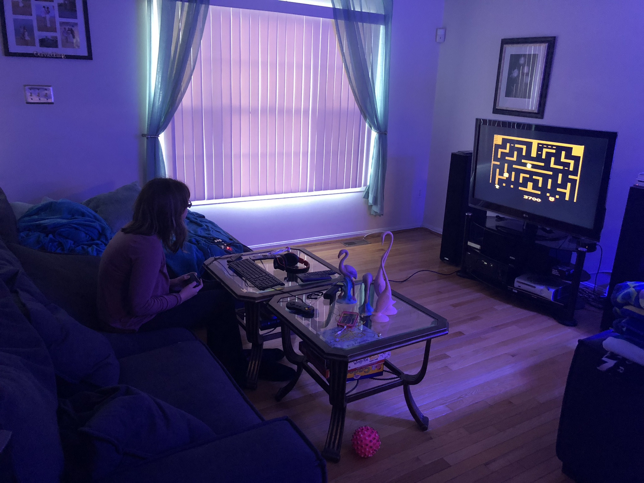
I initially got the raspberry and was immediately distracted by my true natured nerd/cool factor of the device and had to isntall Retro pi https://retropie.org.uk/ that was a couple weeks of lost time but gave me time to source and figure out what I still needed to order as long as do some research.
While the kids where busy with that I dug though the master thread and found all the items I could find that I did not see covered int he adafruit guides. (since then some more adafruit guides have been published that cover this stuff)
Doser control
https://learn.adafruit.com/adafruit-raspberry-pi-lesson-9-controlling-a-dc-motor?view=all
https://www.reef2reef.com/threads/r...-on-raspberry-pi.289256/page-304#post-5069096
PH circuit
https://www.reef2reef.com/threads/r...troller-based-on-raspberry-pi.289256/page-183
https://www.atlas-scientific.com/_files/_datasheets/_circuit/pH_EZO_datasheet.pdf
Mechanical float switch
https://www.reef2reef.com/threads/r...-on-raspberry-pi.289256/page-194#post-4559560
Cron timing
https://www.reef2reef.com/threads/r...troller-based-on-raspberry-pi.289256/page-345
https://healthchecks.io/docs/cron/
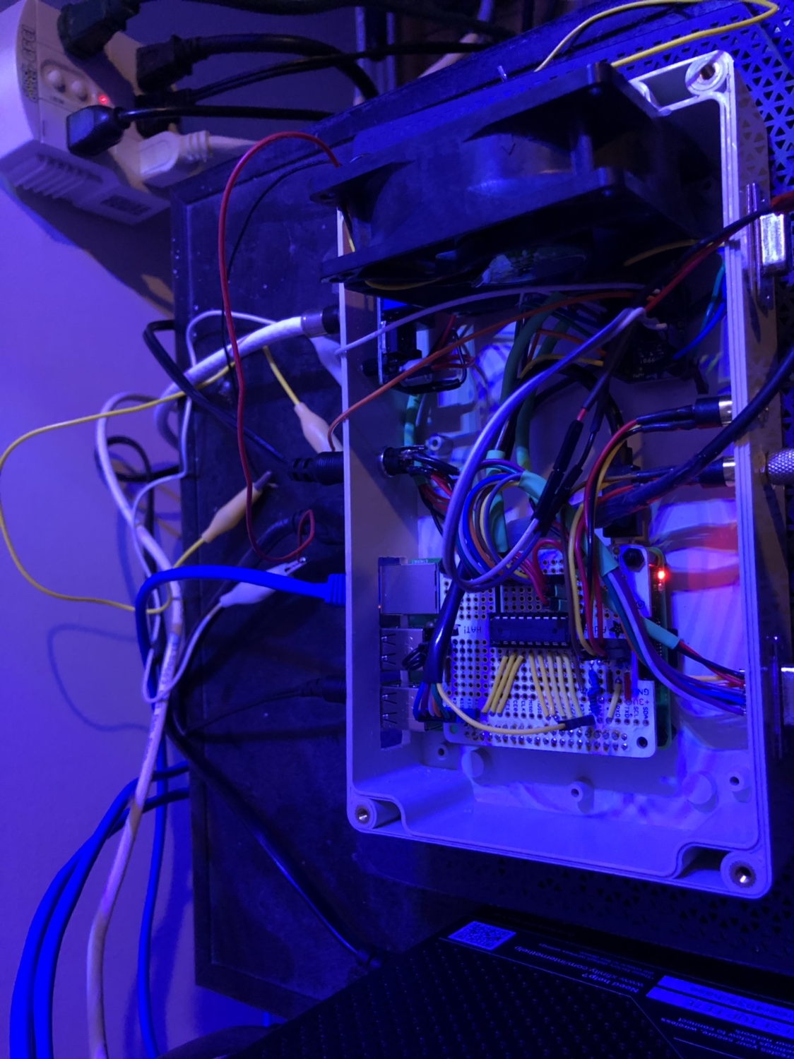
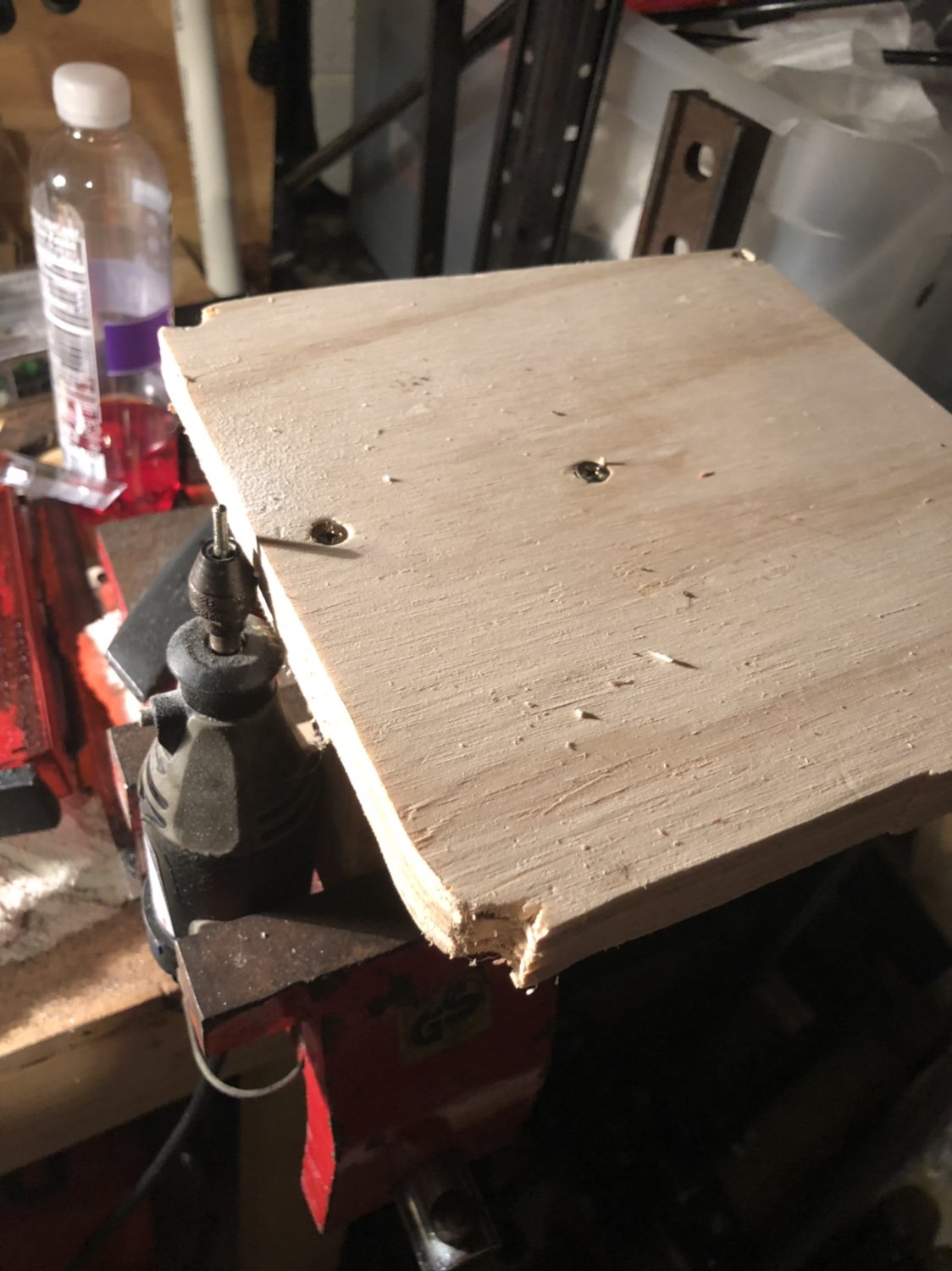
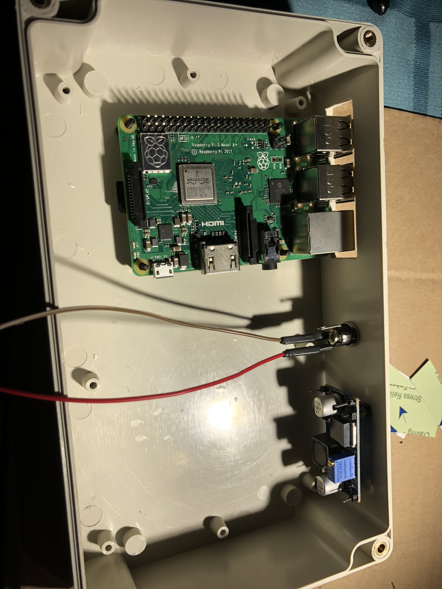
Because I wanted an all encompassing build I was going to need a larger power supply than the recommended 2.5 amp. Based on memory from my highschool electronics days I remembered that current is not output but drawn as needed since I plan to run doser motors that will draw almost one amp by them selves at full load, power relays, the Rpi, and other circuitry I opted for a 5 amp power supply. While it is most likely overkill that will not be needed I know if can provide if needed. Mounting my Rpi I wanted to have full access to all ports and memory card. Since stability is a concern to me and have read about wifi crashing I opted to keep mine wired so needed the Ethernet port exposed. I placed it in the box and used my dremel to cut all the holes needed and started wiring the barrel connector for power.
The Perma Proto pi hat is really cool. It mounts right on top of the Rpi and gives you build space and access to all the pins. Since the raspberry runs off 5 volts and both relays and dosing pumps run off 12 volts an adjustable voltage regulator is required. This gives you 12 volts straight off the power supply and you turn the knob on the regulator to dial in the voltage required to run the pi. Here is the completed HAT with power, dual temperature probes, a single mechanical float switch, and the IC socket for the ULN2803 to drive the relays installed.
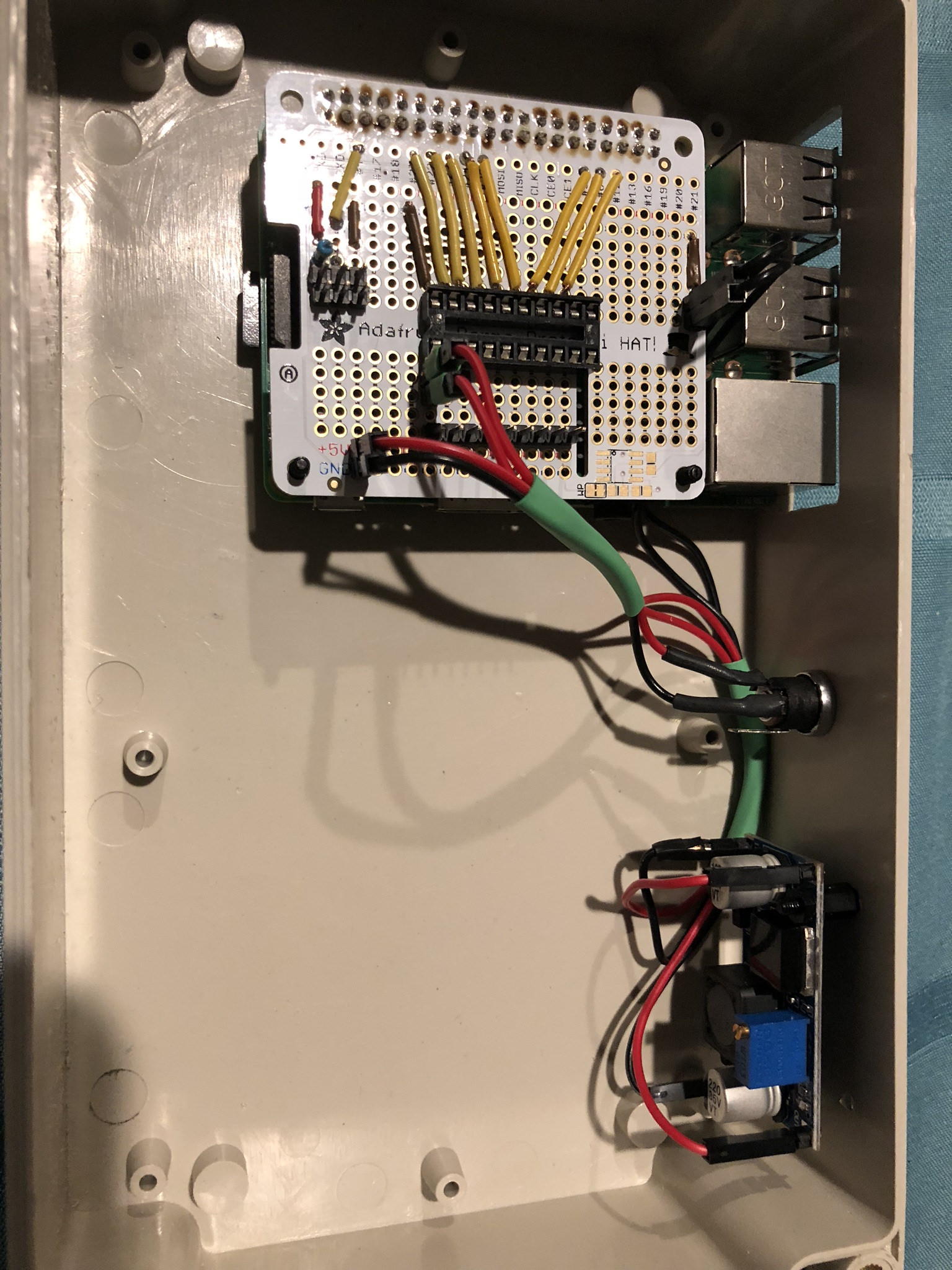
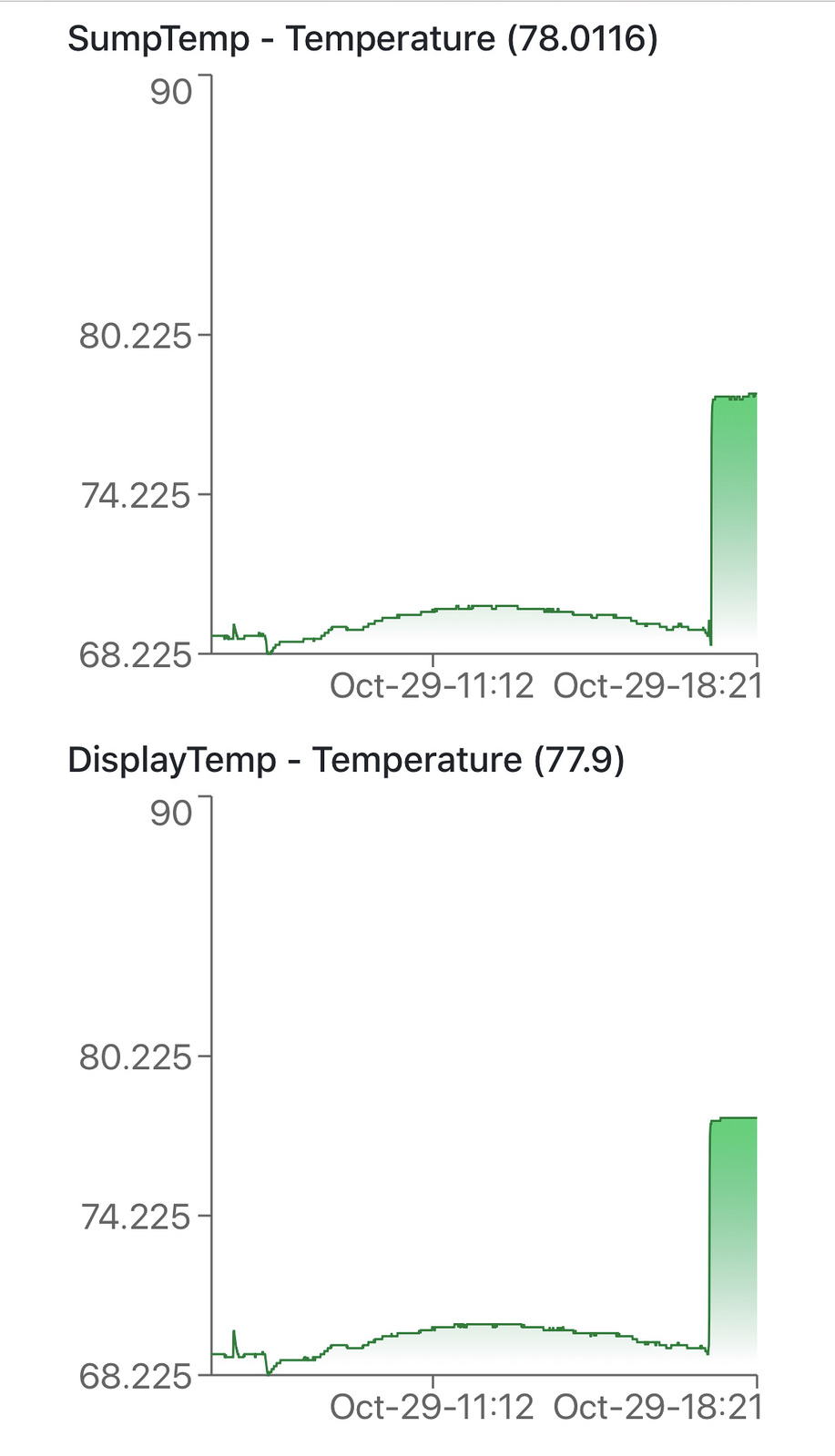
You can run multiple temp probes by simply adding more header pins in parallel. The reef-pi software will pick up the individual address for each probe and allow you to see both readings.
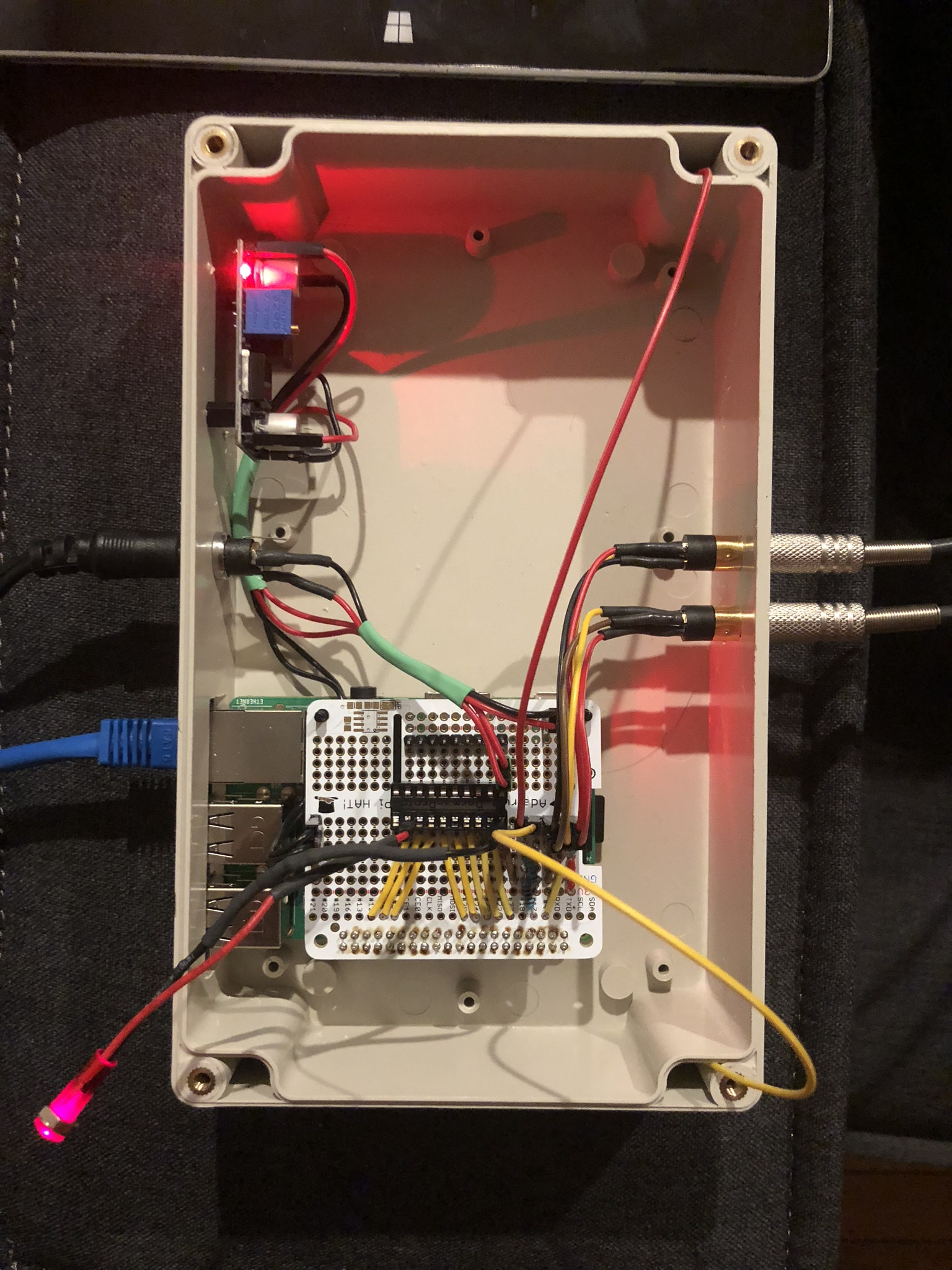
And here is my first power test. I used an LED stuck in the ULN2803 socket to test each outlet with the software to make sure it worked.
I spent several weeks playing around with the software. I left it plugged in, set up rules, messed with web access, built dashboards, etc. The idea was to familiarize myself and see if I could break it or cause it to lock up.
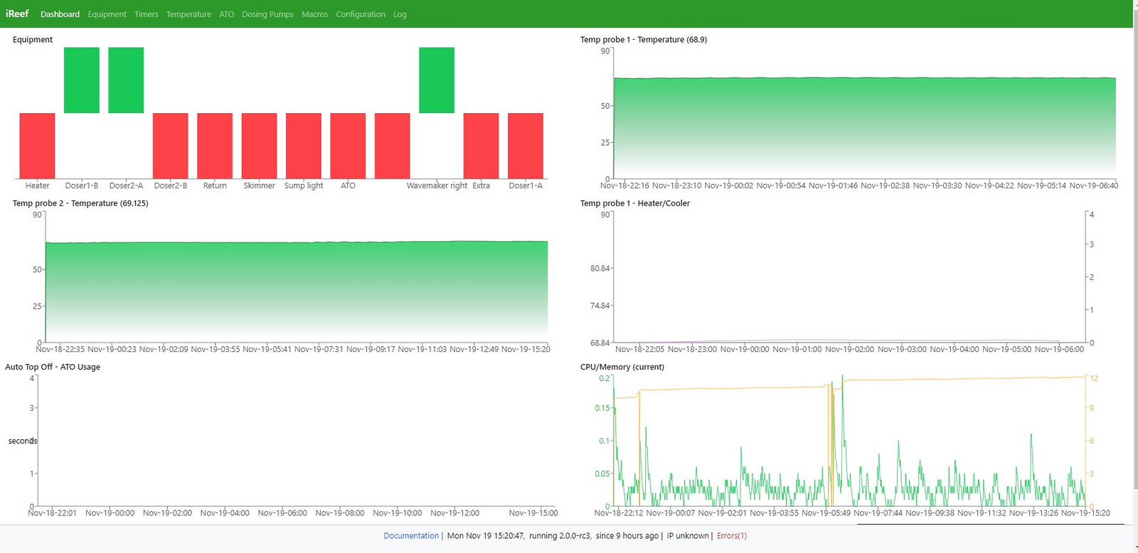
The only thing so far I am not happy about is the stereo plugs recommended in the adafruit guide. I have had nothing but problems with them and keeping reliable connections. I am still researching but plan to upgrade those to something a little more robust. You can see in the above picture that one of my temp probes has gone off line at one point today identified in the error at the bottom of the page.
So doing some research into integrating dosers I have decided to get some high end pumps at some point in the future. But for the time I will be hacking up my jebao doser and using the box as a slave for reef-pi. another thing I remember from highschool is that motors are noisy and can make voltage ripply. I also realized that the motors I want to run have a higher current draw than the L293D chip in the adafruit lesson can handle. I did some more research and found a lot of the people "in the know" lol do not like the antiquated L293D and prefer the MOSFET driven TB6612 which adafruit has a nice break out board for. https://learn.adafruit.com/adafruit-tb6612-h-bridge-dc-stepper-motor-driver-breakout With those two points in mind I wanted to better protect the rpi and set it up with as little noise as possible. The raspberry has a 5 volt output pin that is technically used to power other 5 volt devices connected to it. In the adafruit reef-pi guide this pin is used to also provide 5 volts to the raspberry itself and the protected micro usb port is not used. While it works it bypasses the Raspberry's internal circuit protection, noise filters, and fuse. because I plan on using one power supply for everything and motors are noisy I opted to cut up a micro USB cord and power the pi at the normal micro usb port from the 5 volt regulator. Below is a simple block diagram of what I had in mind.
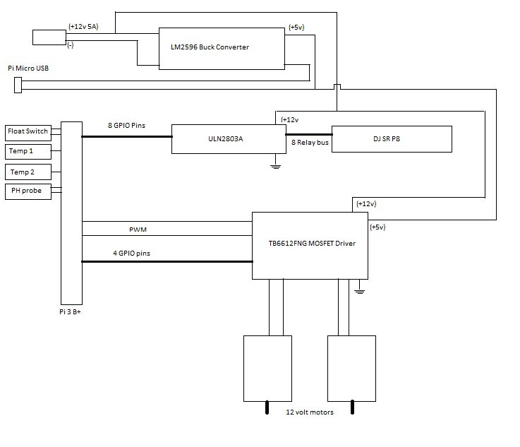
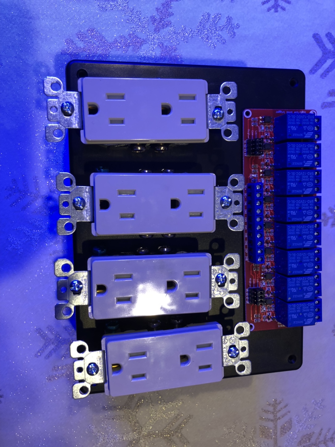
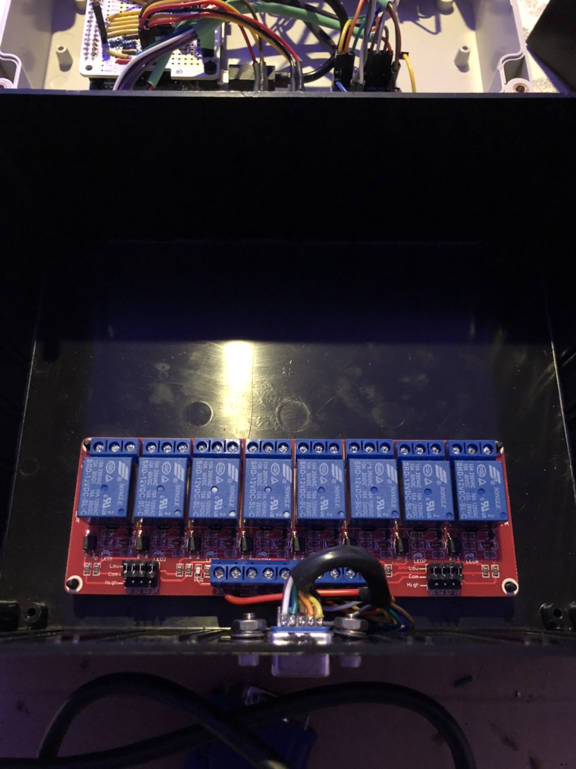
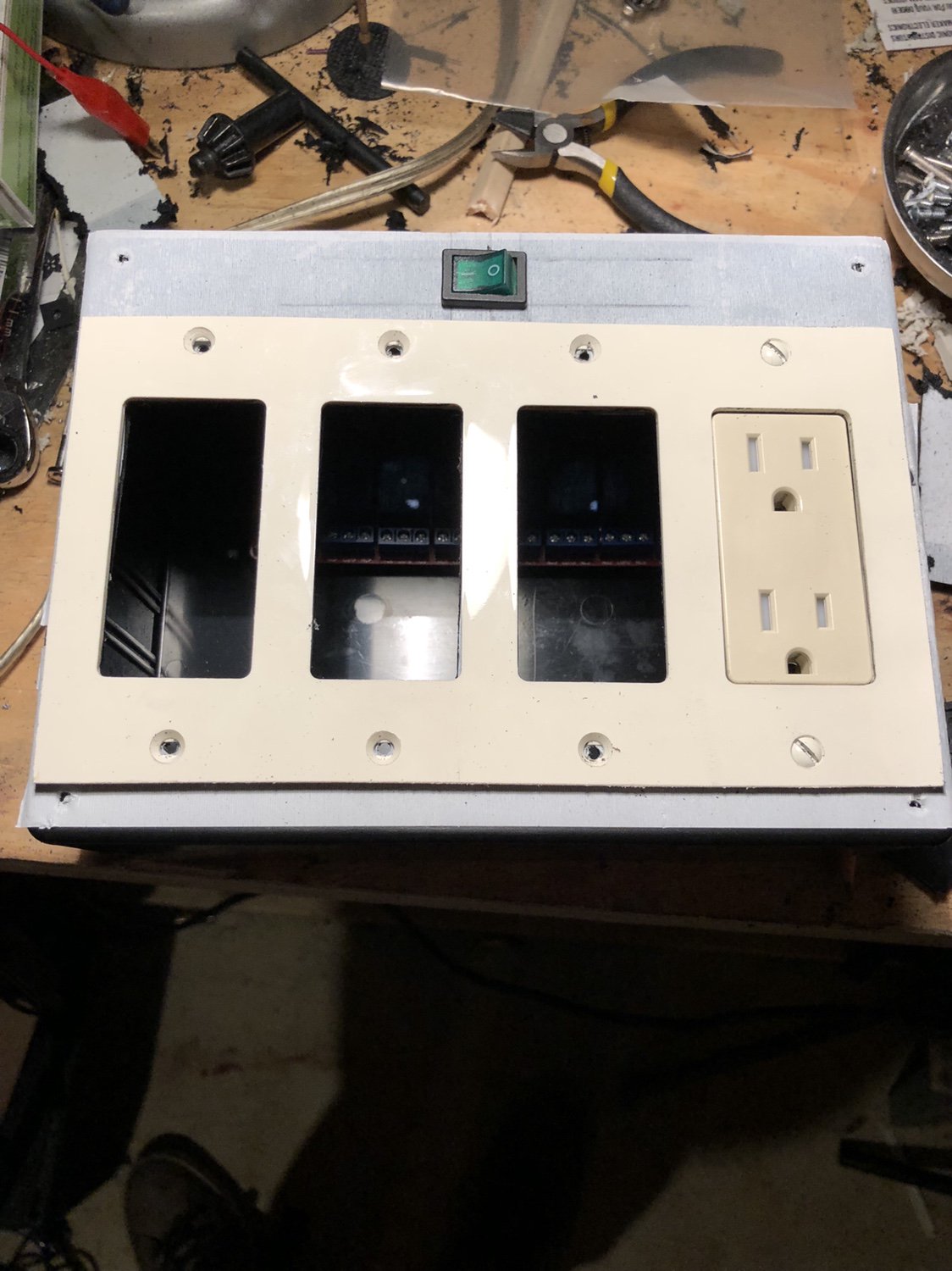
I have since decide not to use the DJ SRP8 power strip and build my own relay box so that I can configure relays to fail open and fail closed. This comes in handy if your reef-pi fails for some reason or is powered off. If a relay fails closed when reef-pi is lost whatever you chose such as return, wavemakers, etc will stay on. Things that should fail open would be things like your heater so if reef-pi fails the heater does not stay on. I also routed all 12 volt devices as close to the power input as possible rather than taking it off a jumper from the pi HAT.
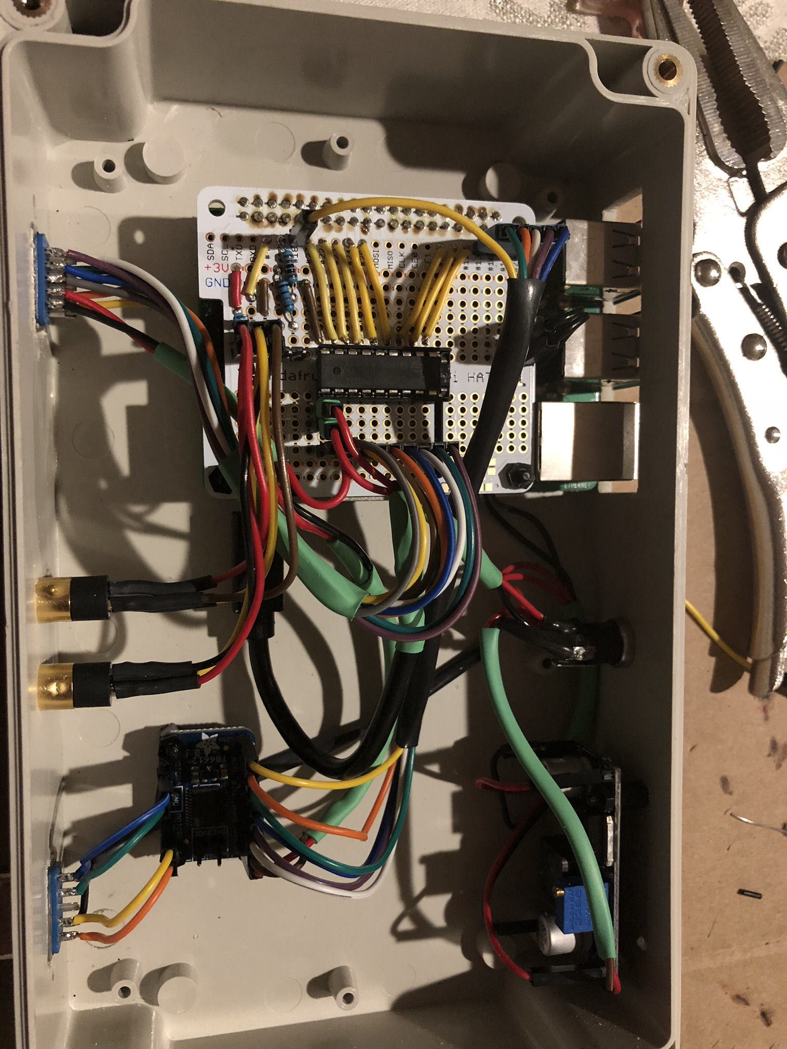
And this is where I sit now. I have a DB style HD 15 plug that will carry 12 volts and ground along with all 8 outputs to my relay box, a DB 9 plug is for a cord to run to the remote doser box. And it also has 12 volts and ground (I am not sure why I wired it for power also, I was tired). I tested both doser circuits with an LED and they work just fine through the TB6612.
I dont have much room left lol but I tried to leave a little extra just in case I want to add more. I still need to add PH monitoring, build the relay box, mod the doser box, and then bench test everything with the motors running and relays working. I was told that eventually there is going to be provisions to link multiple reef-pi's together and control them from one dash board which will be nice. If this all does not work together I will break it out and make separate modules. once this is all working and running I may dive into building a controller for my Ocean Revive lights. So far a quick search shows that the OR lights can only dim to 10% then must be turned off with a relay or timer. I need to do some more digging to see if there is a way around this. If I build a light controller I want to go from nothing to full brightness. Once I get the slave modules built I will post up my progress.
To start the build I ordered a raspberry pi3 B+, box, power supply, and several parts to include resistors, connectors, wires, standofs, etc. My full list is at the following link. http://a.co/3AymdBj
I had a lot of stuff on hand already from both junk parts at work and my own collection of old electronics hardware that for some reason I saved over the years. Some of the things needed that I already had on hand
Soldering iron and solder
wire snips
wire stripper
exacto knife
mini file
Heat gun
Shrink tubing
120volt outlets from any hardware store
dremel w/bits
volt meter
I initially got the raspberry and was immediately distracted by my true natured nerd/cool factor of the device and had to isntall Retro pi https://retropie.org.uk/ that was a couple weeks of lost time but gave me time to source and figure out what I still needed to order as long as do some research.
While the kids where busy with that I dug though the master thread and found all the items I could find that I did not see covered int he adafruit guides. (since then some more adafruit guides have been published that cover this stuff)
Doser control
https://learn.adafruit.com/adafruit-raspberry-pi-lesson-9-controlling-a-dc-motor?view=all
https://www.reef2reef.com/threads/r...-on-raspberry-pi.289256/page-304#post-5069096
PH circuit
https://www.reef2reef.com/threads/r...troller-based-on-raspberry-pi.289256/page-183
https://www.atlas-scientific.com/_files/_datasheets/_circuit/pH_EZO_datasheet.pdf
Mechanical float switch
https://www.reef2reef.com/threads/r...-on-raspberry-pi.289256/page-194#post-4559560
Cron timing
https://www.reef2reef.com/threads/r...troller-based-on-raspberry-pi.289256/page-345
https://healthchecks.io/docs/cron/
Because I wanted an all encompassing build I was going to need a larger power supply than the recommended 2.5 amp. Based on memory from my highschool electronics days I remembered that current is not output but drawn as needed since I plan to run doser motors that will draw almost one amp by them selves at full load, power relays, the Rpi, and other circuitry I opted for a 5 amp power supply. While it is most likely overkill that will not be needed I know if can provide if needed. Mounting my Rpi I wanted to have full access to all ports and memory card. Since stability is a concern to me and have read about wifi crashing I opted to keep mine wired so needed the Ethernet port exposed. I placed it in the box and used my dremel to cut all the holes needed and started wiring the barrel connector for power.
The Perma Proto pi hat is really cool. It mounts right on top of the Rpi and gives you build space and access to all the pins. Since the raspberry runs off 5 volts and both relays and dosing pumps run off 12 volts an adjustable voltage regulator is required. This gives you 12 volts straight off the power supply and you turn the knob on the regulator to dial in the voltage required to run the pi. Here is the completed HAT with power, dual temperature probes, a single mechanical float switch, and the IC socket for the ULN2803 to drive the relays installed.
You can run multiple temp probes by simply adding more header pins in parallel. The reef-pi software will pick up the individual address for each probe and allow you to see both readings.
And here is my first power test. I used an LED stuck in the ULN2803 socket to test each outlet with the software to make sure it worked.
I spent several weeks playing around with the software. I left it plugged in, set up rules, messed with web access, built dashboards, etc. The idea was to familiarize myself and see if I could break it or cause it to lock up.
The only thing so far I am not happy about is the stereo plugs recommended in the adafruit guide. I have had nothing but problems with them and keeping reliable connections. I am still researching but plan to upgrade those to something a little more robust. You can see in the above picture that one of my temp probes has gone off line at one point today identified in the error at the bottom of the page.
So doing some research into integrating dosers I have decided to get some high end pumps at some point in the future. But for the time I will be hacking up my jebao doser and using the box as a slave for reef-pi. another thing I remember from highschool is that motors are noisy and can make voltage ripply. I also realized that the motors I want to run have a higher current draw than the L293D chip in the adafruit lesson can handle. I did some more research and found a lot of the people "in the know" lol do not like the antiquated L293D and prefer the MOSFET driven TB6612 which adafruit has a nice break out board for. https://learn.adafruit.com/adafruit-tb6612-h-bridge-dc-stepper-motor-driver-breakout With those two points in mind I wanted to better protect the rpi and set it up with as little noise as possible. The raspberry has a 5 volt output pin that is technically used to power other 5 volt devices connected to it. In the adafruit reef-pi guide this pin is used to also provide 5 volts to the raspberry itself and the protected micro usb port is not used. While it works it bypasses the Raspberry's internal circuit protection, noise filters, and fuse. because I plan on using one power supply for everything and motors are noisy I opted to cut up a micro USB cord and power the pi at the normal micro usb port from the 5 volt regulator. Below is a simple block diagram of what I had in mind.
I have since decide not to use the DJ SRP8 power strip and build my own relay box so that I can configure relays to fail open and fail closed. This comes in handy if your reef-pi fails for some reason or is powered off. If a relay fails closed when reef-pi is lost whatever you chose such as return, wavemakers, etc will stay on. Things that should fail open would be things like your heater so if reef-pi fails the heater does not stay on. I also routed all 12 volt devices as close to the power input as possible rather than taking it off a jumper from the pi HAT.
And this is where I sit now. I have a DB style HD 15 plug that will carry 12 volts and ground along with all 8 outputs to my relay box, a DB 9 plug is for a cord to run to the remote doser box. And it also has 12 volts and ground (I am not sure why I wired it for power also, I was tired). I tested both doser circuits with an LED and they work just fine through the TB6612.
I dont have much room left lol but I tried to leave a little extra just in case I want to add more. I still need to add PH monitoring, build the relay box, mod the doser box, and then bench test everything with the motors running and relays working. I was told that eventually there is going to be provisions to link multiple reef-pi's together and control them from one dash board which will be nice. If this all does not work together I will break it out and make separate modules. once this is all working and running I may dive into building a controller for my Ocean Revive lights. So far a quick search shows that the OR lights can only dim to 10% then must be turned off with a relay or timer. I need to do some more digging to see if there is a way around this. If I build a light controller I want to go from nothing to full brightness. Once I get the slave modules built I will post up my progress.