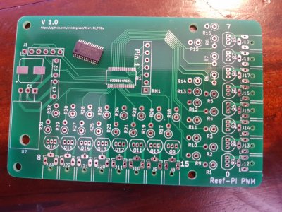
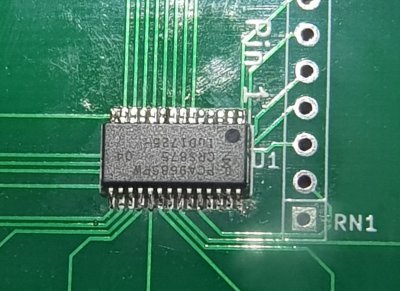
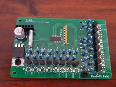
Buddy's Reef-Pi Build

wykat

Active Member
View Badges
Joined
May 23, 2018
Messages
182
Reaction score
421
Rating - 0%
0   0   0
Sorry I misunderstood which connection you wanted me to check on the I2C, I can definitely confirm that I have a connection to ground on pin6.
I have uploaded a picture of one of my spare boards just to confirm this with you.
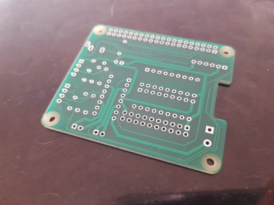
20181206_062322.jpg

I removed the ULN chips and put a jumper wire in the sockets as you described.
The relay does work in normal and reversed mode!
After this, I tried a brand new ULN chip but then the relay does not work again. You must be right in saying that my relay board does not like the ULN chips.

Do you think there is an alternative solution to getting the chips working with the board or will I need to buy different boards?
1) Yes that Reef-PI_HAT board is ok!

2) Good to hear it worked with the short cut. For your reference, this is the schematic for your relay board:
upload_2018-12-6_8-11-57.png

In 'your' relay board the relay must be activated by putting an active 5V signal from the bottom. I think that if you connect the relay board with the HAT, you will see the power led on the relay board to go on (normal GND/5V power from the HAT), but you will never see the LED's from the relays to turn on. So it looks like the ULN doesn't drive the 5V (that's what I still have to look into).

This is the design from the working relay boards:
upload_2018-12-6_8-18-48.png

Basically the ULN 'tears down' the voltage on IN1 and then activates the relay. What I don't understand is how this can work without the GND connected to the relay board, but in fact it does. ;)

I'm not an expert on relays here, but in my view your present relay board has limited protection from spikes generated by the coil in the relay while switching.
Will need to better understand the functionality of the ULN2803 chip (just copied the fritzing design) in order to understand if there is a way to generate a 5V output but I'm afraid it can't.
 

wykat

Active Member
View Badges
Joined
May 23, 2018
Messages
182
Reaction score
421
Rating - 0%
0   0   0
OP
OP
buddy.

buddy.

Active Member
View Badges
Joined
May 16, 2018
Messages
291
Reaction score
617
Location
Australia
Rating - 0%
0   0   0
1) Yes that Reef-PI_HAT board is ok!

2) Good to hear it worked with the short cut. For your reference, this is the schematic for your relay board:
upload_2018-12-6_8-11-57.png

In 'your' relay board the relay must be activated by putting an active 5V signal from the bottom. I think that if you connect the relay board with the HAT, you will see the power led on the relay board to go on (normal GND/5V power from the HAT), but you will never see the LED's from the relays to turn on. So it looks like the ULN doesn't drive the 5V (that's what I still have to look into).

This is the design from the working relay boards:
upload_2018-12-6_8-18-48.png

Basically the ULN 'tears down' the voltage on IN1 and then activates the relay. What I don't understand is how this can work without the GND connected to the relay board, but in fact it does. ;)

I'm not an expert on relays here, but in my view your present relay board has limited protection from spikes generated by the coil in the relay while switching.
Will need to better understand the functionality of the ULN2803 chip (just copied the fritzing design) in order to understand if there is a way to generate a 5V output but I'm afraid it can't.
Thanks for that explanation :) So do you think I am better off not using my boards and buying the ones that we know will work?
 

wykat

Active Member
View Badges
Joined
May 23, 2018
Messages
182
Reaction score
421
Rating - 0%
0   0   0
Thanks for that explanation :) So do you think I am better off not using my boards and buying the ones that we know will work?
Yes I think it's better to use the known working boards.

I looked at the ULN2803 datasheet an in order to get some positive voltage out of it would require a pull up resistor. You could give it a try by adding a 100 ohm resistor between 5V and the relay input (this would cause the ULN2803 to drop the voltage with only 50mA). Nevertheless I don't think this is a clean solution as 16 parallel relays would take 0.8A.
 
OP
OP
buddy.

buddy.

Active Member
View Badges
Joined
May 16, 2018
Messages
291
Reaction score
617
Location
Australia
Rating - 0%
0   0   0
Yes I think it's better to use the known working boards.

I looked at the ULN2803 datasheet an in order to get some positive voltage out of it would require a pull up resistor. You could give it a try by adding a 100 ohm resistor between 5V and the relay input (this would cause the ULN2803 to drop the voltage with only 50mA). Nevertheless I don't think this is a clean solution as 16 parallel relays would take 0.8A.
No worries, I think you are right and it would just be better to get the new boards.
Hopefully I can find a use for my current boards for something in the future!
 

Bigtrout

Valuable Member
View Badges
Joined
Dec 16, 2018
Messages
1,189
Reaction score
2,826
Rating - 0%
0   0   0
No worries, I think you are right and it would just be better to get the new boards.
Hopefully I can find a use for my current boards for something in the future!
Do you have a link to your boards?

I have seen several boards on amazon, most are like wykats which are activated when an input pin is driven low(0 volts) which is what the uln2803 does. When you put 3.3 volts on the input of the uln, the corresponding output is driven to ground. It is called a logic inverter or high output darlington transistor array...
There are also 8 relay boards being sold that have jumpers to select whether the relay activates on a high or low signal.

All that being said, the wykat linked board works with the uln2803, and because it uses octocouplers, it is in a sense double isolated from the raspberry pi which is always a good thing!
 

Bigtrout

Valuable Member
View Badges
Joined
Dec 16, 2018
Messages
1,189
Reaction score
2,826
Rating - 0%
0   0   0
Hey @Bigtrout thanks for that explanation. These are the boards that I have.
Ok looking at those, they do indead appear to be triggered on a high signal direct from the raspberry pi...that is a 3.3 volt signal is needed to activate the relay, so the uln2803 would not work easily because it inverts the signal and as wykat said, although it would work without it, there is little protection for the outputs of the pi when the coils of the relay activate and deactivate, it may cause voltage spikes to go back thru the outputs, and directly driving all the relays you are using alot of power thru the gpio pins. So without some additional circuitry the low signal driven boards used with the uln2803 is a cleaner and better solution.

This relay is one like wykat uses:
https://www.littlebird.com.au/8-channel-5v-relay-shield-module-c6c8c2d1-5482-433f-890c-5923fb855721
 
Last edited:
OP
OP
buddy.

buddy.

Active Member
View Badges
Joined
May 16, 2018
Messages
291
Reaction score
617
Location
Australia
Rating - 0%
0   0   0
First attempt and I don't have any shorts but I think I fried the chip because I am getting nothing on the I2C detection. I'm getting 5v to the board though.
I'll have another go later with a new board and chip.

20181223_131313.jpg
 

theatrus

Valuable Member
View Badges
Joined
Mar 26, 2016
Messages
1,957
Reaction score
3,355
Location
Sacramento, CA area
Rating - 0%
0   0   0
First attempt and I don't have any shorts but I think I fried the chip because I am getting nothing on the I2C detection. I'm getting 5v to the board though.
I'll have another go later with a new board and chip.

20181223_131313.jpg

Some of those leads may not be soldered down to the pads - the pad looks clean and the lead has solder. I'd add some flux if you have it, and try again.

A tell-tale sign is to poke the lead with a pair of tweezers, if it moves its not tacked down right.
 

wykat

Active Member
View Badges
Joined
May 23, 2018
Messages
182
Reaction score
421
Rating - 0%
0   0   0
Some of those leads may not be soldered down to the pads - the pad looks clean and the lead has solder. I'd add some flux if you have it, and try again.

A tell-tale sign is to poke the lead with a pair of tweezers, if it moves its not tacked down right.
Agree, I also doubt that the chip is fried after what I've done to some. Since the I2C interface only requires 4 wires, please verify following connections:
Pin 14 to GND (pin 6 on J1)
Pin 28 to 5V (pin 2 on J1)
Pin 27 to pin 3 on J1
Pin 26 to pin 4 on J1

for the rest soldering looks great (except pins 13/14 it's hard to see)
 
OP
OP
buddy.

buddy.

Active Member
View Badges
Joined
May 16, 2018
Messages
291
Reaction score
617
Location
Australia
Rating - 0%
0   0   0
Some of those leads may not be soldered down to the pads - the pad looks clean and the lead has solder. I'd add some flux if you have it, and try again.

A tell-tale sign is to poke the lead with a pair of tweezers, if it moves its not tacked down right.
Agree, I also doubt that the chip is fried after what I've done to some. Since the I2C interface only requires 4 wires, please verify following connections:
Pin 14 to GND (pin 6 on J1)
Pin 28 to 5V (pin 2 on J1)
Pin 27 to pin 3 on J1
Pin 26 to pin 4 on J1

for the rest soldering looks great (except pins 13/14 it's hard to see)
Thanks. I just tested those and every other pin while I was at it and they all have a connection with where are they supposed to. Tried to detect again and nothing.

I soldered a new chip on a new board and this time success!! I guess I either fried the chip with heat (most likely!) or it was faulty.

i2cdetect.PNG
 
OP
OP
buddy.

buddy.

Active Member
View Badges
Joined
May 16, 2018
Messages
291
Reaction score
617
Location
Australia
Rating - 0%
0   0   0
PWM works as expected:D

I used an old project box to save on costs but it isn't tall enough to stack the PWM board.

I am waiting on a few plugs and connectors, along with my new relay boards to arrive so this will be it until after Xmas.

20181223_210831.jpg
 
OP
OP
buddy.

buddy.

Active Member
View Badges
Joined
May 16, 2018
Messages
291
Reaction score
617
Location
Australia
Rating - 0%
0   0   0
For anyone interested, I used the solder wick method to solder the chip in place. I just have a cheap pointy tip soldering iron and didn't use any flux.
Just be careful not to use too much heat!
 

High pressure shells: Do you look for signs of stress in the invertebrates in your reef tank?

  • I regularly look for signs of invertebrate stress in my reef tank.

    Votes: 36 31.3%
  • I occasionally look for signs of invertebrate stress in my reef tank.

    Votes: 28 24.3%
  • I rarely look for signs of invertebrate stress in my reef tank.

    Votes: 21 18.3%
  • I never look for signs of invertebrate stress in my reef tank.

    Votes: 30 26.1%
  • Other.

    Votes: 0 0.0%
Back
Top