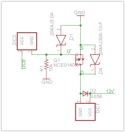

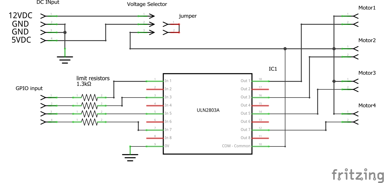
I want to build a DIY Doser, similarly to the Adafruit Guide. Sadly I couldn't find L293 ICs, so I decided to run with standard monodirectional bipolar transistors (ULN2801 with input resistors).
The current plan and circuit diagram can be found on my project's GitHub page.
A few quirks:
I remember @robsworld78 mentioning something like this in one of his great videos here.
The current plan and circuit diagram can be found on my project's GitHub page.
A few quirks:
- I'm concerned about the PCA9685's reliability over I2C, I therefore want to run the pumps on the PI's GPIOs
- My Pumpsrun nominally on 12V, 200-300mA and 100ml/min, e.g. 0.6s / ml
- I'm concerned that this is way to fast for typical daily dosing of trace elements
- I therefore have several methods, as far as I can see
- dose less often with a then higher amount
- dose more often, but with diluted fluid (as @Ranjib)
- decrease the pumps' speed
- I'm currently favoring to decrease the pump speed
- I could do this via PWM
- uses more parts and makes the circuit more complicated
- I could simply run the pumps with 5V instead of the nominal 12V
- If the resistance stays the same (which it probably won't) I decrease the electrical power by ( 5v/12V )^2 which is about 1/100
- that means I would instead of dosing 1ml every 0.6 seconds, dose 1ml every 6-60 seconds, depending on how the pump reacts
- I could do this via PWM
I remember @robsworld78 mentioning something like this in one of his great videos here.
Last edited:


") 5v sounds a little low for a 12v pump, on my controller the ports turn down to 6v but the motor starts making noises and has trouble starting up. I've had a few cheap versions and some run better than others so mileage will vary. If you go this route maybe have the minimum 7v. Either way I'm sure you'll come up with something.
5v sounds a little low for a 12v pump, on my controller the ports turn down to 6v but the motor starts making noises and has trouble starting up. I've had a few cheap versions and some run better than others so mileage will vary. If you go this route maybe have the minimum 7v. Either way I'm sure you'll come up with something.