My temperature data has stopped updating on the dashboard and has reverted to showing data from 2 days ago. This happened after a restart. (I AM getting data pushed to Adafruit.io, so I know it is working. The CPU/Memory data on the Dashboard is updating correctly.
Navigation
Install the app
How to install the app on iOS
Follow along with the video below to see how to install our site as a web app on your home screen.
Note: This feature may not be available in some browsers.
More options
You are using an out of date browser. It may not display this or other websites correctly.
You should upgrade or use an alternative browser.
You should upgrade or use an alternative browser.
reef-pi :: An opensource reef tank controller based on Raspberry Pi.
- Thread starter Ranjib
- Start date
-
- Tags
- controller raspberry-pi
- Tagged users Ranjib
I too have had this issue on restarting. Usually reappears after awhile or i have to plug and replug a couple times. After its working it works.
No, there is no board that will increase the number of GPIO. The popular IO expansion board that have no soeciak IC in them are just physical length extension boards., i.e. they spread out the Isame pins in larger surface area, making it easy to solder/connect jumper wires
There are special ICs that can increase the number I/O pins, example will be MCP23017 IC. Each of those ICs will add 16 pins to Pi, but to support those reef-pi needs special code and configuration support (like users should be able to specify that this pin belongs to mcp23017 ) etc. We have not required this yet.
Ok, then I only show 4 available GPIO pins other than the ones that marked for UART, PCM, SPI or PCM. Can I use those "special" GPIO pins?
- Joined
- Mar 15, 2018
- Messages
- 1
- Reaction score
- 1
Power is our main concern here. Each of the relays draw 15-20ma current. It is recommended that the total current draw from GPIO (we need 1 for each relay) to be less than 50-70ma. I would recommend use a transistor for each channel and use the GPIO to control the transistor . Thus the current draw from GPIO will be less, and you probably have ample current from the 5v rail , I am assuming you are using a beefier power supply (say 5v 2.4a).
In short, you need 1 common npn transistor per channel, 1 2.2k resistor, 1 10K resistor. So, total 8 transistor (2n222a), 8 10K resistor, 8 2.2 k resistor, I would also note that we have had 16 channel relay working without this, but its probably not safe or durable. You can use this as reference:
https://docs.google.com/file/d/0B5-HND9HJkXWSTQtYlFTZ3VyODA/edit
Let me know if you have any question,
Hi Ranjib,
first, thanks a lot for reefPi I use if for a freshwater tank and it is working great.
As for the relay connection, I am using a Darlington array to drive the relay via the Raspberry Pi.
This has two advantages:
- the current per GPIO line is about 2 mA
- it can be safely used by the 3.3 V Raspberry GPIO (I have seen a smoking Raspberry Pi driving an 8-channel 5V relay originally intended for an Arduino)
So fat I have made very good experience with a ULN2803A - which also happen to be a breeze zo connect
I had started wave maker related work on the software side, but its stalled due to me prioritizing the pH work. I am thinking of this for the wave maker:@Ranjib have you added a controller to integrate wave makers to the reef pi yet? I'm just asking as I have 2 Jeabo RW15 in my tank and was wondering if I could use the PWM off my servo board to controll this which in turn could run my wave makers https://www.ebay.co.uk/itm/LMD18200T-DC-Motor-Driver-Module-Board-PWM-Adjustable-Speed-for-Arduino-DIY/331570181509?ssPageName=STRK:MEBIDX:IT&_trksid=p2060353.m1438.l2649
Or is there a better way of doing it?
- Circuit wise, its not very different from Kessil controller, we can use either Pi (has two pwm output) or existing pca9685 pins (16) for pwm generation. this needs to be adjusted for the target wavemaker power. For jebao this is 24V , 700ma. So, a 24v power adapter, a tip120 and couple of resistor should be bare bone requirement on the circuit side. This is if we intend to drive the power head directly, if we instead use the jebao's controller to do the conversion and if it can feed in 10v pwm or 5v pwm like meanwell driver we can do away with same circuit as kessil controller. But this is one of the very many possibilities that will only work with jebao (it is possible to use straight wifi to control them as well, like how the jebao controller make master-slave among themselves). I am also not sure if this will work with anything else. And the price point of jebao's own controller is so less that I felt i should discuss this more before investing much
- On the software side, I think I'll introduce a api to specify arbitrary profiles (speed values across a fixed time interval. Say, 10 values at 1 minute intervals). And then use can attach the profiles , combine and repeat them to drive a pump. The current lighting cycle is a special case for this (12 interval, each at 2 hours).
In short, this will take few month at least to solidify, unless someone else from community wants to headstart this. If you want to play around with this or want to check if the assumptions are right or wrong, you can use a jebao pump and the lighting UI for reef-pi and construct the circuit appropirately and then test it against a jebao pump.
Yes you can , but then you'll loose their special capability. We dont use UART so that is relatively safer to use . Same goes for SPI pins. PCM is used for PWM , dimming using RPI , if you are using pca9685 chipset , you can use that as well. You have to configure Pi to make these changes (raspi-config) , disable spi/uartOk, then I only show 4 available GPIO pins other than the ones that marked for UART, PCM, SPI or PCM. Can I use those "special" GPIO pins?
OohHi Ranjib,
first, thanks a lot for reefPi I use if for a freshwater tank and it is working great.
As for the relay connection, I am using a Darlington array to drive the relay via the Raspberry Pi.
This has two advantages:
A disadvantage, so to say, is that the Darlington array inverts the logic.
- the current per GPIO line is about 2 mA
- it can be safely used by the 3.3 V Raspberry GPIO (I have seen a smoking Raspberry Pi driving an 8-channel 5V relay originally intended for an Arduino)
So fat I have made very good experience with a ULN2803A - which also happen to be a breeze zo connect
I think the logic reversal will happen in normal npn transistor as well. I would say that it come in a DIP package also makes it bit harder for DIY builds. You have to solder a header to make things look ok. But still, this is significantly better for builds with more than 4 channel rleays
Yes you can , but then you'll loose their special capability. We dont use UART so that is relatively safer to use . Same goes for SPI pins. PCM is used for PWM , dimming using RPI , if you are using pca9685 chipset , you can use that as well. You have to configure Pi to make these changes (raspi-config) , disable spi/uart
Perfect! I've got all 16 relays + temp probe working now!
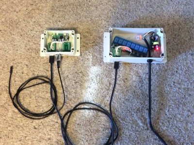
@theatrus has been kind enough to design a PCB for reef-pi based pico controller base board. It is intended for a pico tank, and supports minimal automation including:
- 1 kessil control (two channel 0-10v analog output)
- 1 temperature sensor connector (audio jack)
- 1 ATO sensor (JST/push connector)
- 1 hdmi output to connect with power bars (relay / ac110 v circuits)
This is vastly superior to our common DIY circuits. It has a full blown power circuit (voltage protections, current buffers), whole lot more safety circuits (esd protection, i2c buffers) and unlike 10v pwm, it actually produces 0-10v analog output (i am yet to see the difference). I am super excited to see this,
we are still in prototype mode, hopefully he'll get something out for maker faire

I know it might look straight from bronze age after this, but I'll continue posting my very advance perf /perma proto board based build details
- 1 kessil control (two channel 0-10v analog output)
- 1 temperature sensor connector (audio jack)
- 1 ATO sensor (JST/push connector)
- 1 hdmi output to connect with power bars (relay / ac110 v circuits)
This is vastly superior to our common DIY circuits. It has a full blown power circuit (voltage protections, current buffers), whole lot more safety circuits (esd protection, i2c buffers) and unlike 10v pwm, it actually produces 0-10v analog output (i am yet to see the difference). I am super excited to see this,
we are still in prototype mode, hopefully he'll get something out for maker faire
I know it might look straight from bronze age after this, but I'll continue posting my very advance perf /perma proto board based build details
Not now, this is something slated for 2.0 releaseCan i use more than one temp probe
That is a very nice looking board, and I love the extra features integrated to it.@theatrus has been kind enough to design a PCB for reef-pi based pico controller base board. It is intended for a pico tank, and supports minimal automation including:
- 1 kessil control (two channel 0-10v analog output)
- 1 temperature sensor connector (audio jack)
- 1 ATO sensor (JST/push connector)
- 1 hdmi output to connect with power bars (relay / ac110 v circuits)
This is vastly superior to our common DIY circuits. It has a full blown power circuit (voltage protections, current buffers), whole lot more safety circuits (esd protection, i2c buffers) and unlike 10v pwm, it actually produces 0-10v analog output (i am yet to see the difference). I am super excited to see this,
we are still in prototype mode, hopefully he'll get something out for maker faire

I know it might look straight from bronze age after this, but I'll continue posting my very advance perf /perma proto board based build details
Just a note, when I had the RC Low-pass filter set up on my light control, it would not dim as expected. When I took it off and went back to 10V PWM, my SBReefLights BB dimmed as expected.
hmm... i'll note this. this is not lpf, its op amp based analog converter. But still, we have to test it outThat is a very nice looking board, and I love the extra features integrated to it.
Just a note, when I had the RC Low-pass filter set up on my light control, it would not dim as expected. When I took it off and went back to 10V PWM, my SBReefLights BB dimmed as expected.
I am also routing the RPi PWM puns out of the HDMI connector as well, without filtering, at 0-5V logic levels. It’s still only the two pins from the Pi (shared).
- Joined
- Feb 9, 2018
- Messages
- 31
- Reaction score
- 16
(2) the timer function does not seem to be working.
Last edited:
Ranjib, I’ve been doing some thinking about the way the relay curcuits work, the amperage draw, and the safety of the total load on the reef-pi. So I took mine apart and this is what I come up with:
Using this relay, the total draw is only 2.1mA, and this is with a 100 watt light plugged in (to outlet 1 of the power bar) just in case a load made a difference. The total draw with all 8 relays on at once would only be 16.8 mA.


Also, if set up like mine (with power being supplied from the PSU in the power bar) the current is not being supplied from the 5v pin on RPI. The RPI is supplying only a path to ground to complete the circuit (which also goes back to the power bar PSU).

Either way, power usage from our setup should not be a problem for the RPI itself.
Please feel free to tell me if I have missed something?
Using this relay, the total draw is only 2.1mA, and this is with a 100 watt light plugged in (to outlet 1 of the power bar) just in case a load made a difference. The total draw with all 8 relays on at once would only be 16.8 mA.
Also, if set up like mine (with power being supplied from the PSU in the power bar) the current is not being supplied from the 5v pin on RPI. The RPI is supplying only a path to ground to complete the circuit (which also goes back to the power bar PSU).

Either way, power usage from our setup should not be a problem for the RPI itself.
Please feel free to tell me if I have missed something?
The one thing that could make the difference is that I’m not powering the relay module from the 5v GPIO pin. It is powered from a PSU in the power bar. What I need to do next is to measure the current draw on the input side of the relay and confirm the total draw of the entire relay module.
If it is the case that the total draw is more than the control side of the circuit, it might be a good idea to power them separately as I have done. Rather than from the 5v pin.
I’ll do more testing and get back to everyone.
If it is the case that the total draw is more than the control side of the circuit, it might be a good idea to power them separately as I have done. Rather than from the 5v pin.
I’ll do more testing and get back to everyone.
This is a very good finding. I know theres something missing as most of us are running the setup this way and its working fine. Since there is no standard relay vendor we recommend, its kinda hard to guess the current draw. Most vendor in amazon claims 20ma current draw, which is cause of the concern. What relay you are using? If its from a reputed brand , i'll prefer to make it part of recommended BOMRanjib, I’ve been doing some thinking about the way the relay curcuits work, the amperage draw, and the safety of the total load on the reef-pi. So I took mine apart and this is what I come up with:
Using this relay, the total draw is only 2.1mA, and this is with a 100 watt light plugged in (to outlet 1 of the power bar) just in case a load made a difference. The total draw with all 8 relays on at once would only be 16.8 mA.


Also, if set up like mine (with power being supplied from the PSU in the power bar) the current is not being supplied from the 5v pin on RPI. The RPI is supplying only a path to ground to complete the circuit (which also goes back to the power bar PSU).

Either way, power usage from our setup should not be a problem for the RPI itself.
Please feel free to tell me if I have missed something?
- Joined
- Jul 7, 2017
- Messages
- 106
- Reaction score
- 68
Re-reading over the 193 pages of posts, it looks like 4 people have tried the black box leds with varying degrees of success. Did anyone ever figure out how to get them to dim/ramp without buzzing noises, and smoothly go between values on the reef pi slider? Here are pictures of my black box leds. I can't tell if people are sending the vdim+ / - signals from the pca9685 digitally or with an analog converter. Do we have a fritz diagram for the black boxes with 4 wires? Did we decide we need a 12 volt or 10 volt power supply, and does it require a voltage regulator to drop from 12 to 10. The black box posts are very confusing. Please help.
Thanks!!!


Thanks!!!
Similar threads
- Replies
- 8
- Views
- 169


