I 'll echo my thoughts on this, as I did the slack channel.
I think of three flavors (main boards):
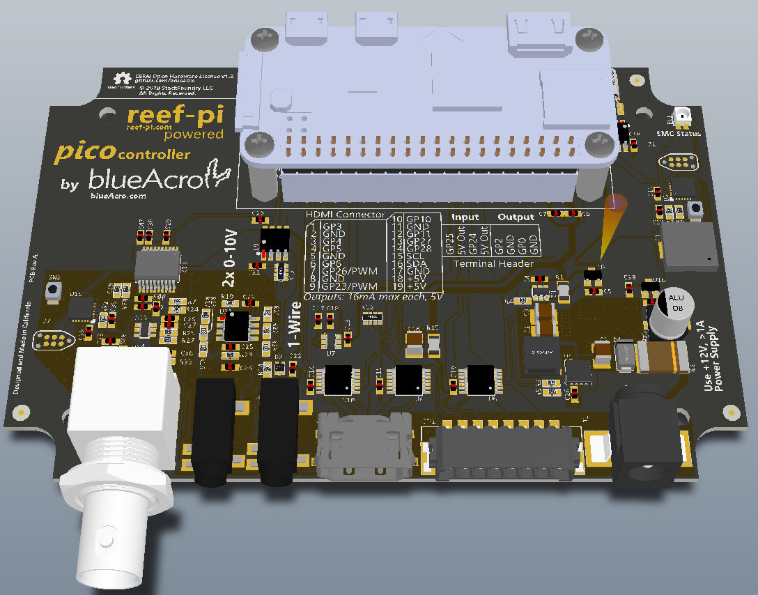
- Pico: Aimed for 5-10G pico tanks. Minimal cost, minimal features (4-8 outlets, temperature, 2 pwm [using pi itself], 1 ato). Our aim here is to support a low-cost pico tank (softies, lps mostly).
- Nano: Aimed for tanks up to 30G. Everything therein pico + ph + doser . More outlets, more pwm (pca9685 integration). I am still not decided on what the exact number of outlets (probably 8-16) and PWM jacks will be.
- Standard: Aimed for 120G+ tanks. Provides everything that reef-pi can do, including the experimental things (every feature of nano in higher volume, i.e. more outlets, ph probes, dosing pumps, wave makers). This assumed a multiple physical unit system. I have very little idea about how this will be, I am likely to think about this more as and when pico board is done, and we have learned some lessons, and nano board's idea is solidified.
Not to mention, it is possible to combine multiple of these units. Also, I am making its explicitly possible each module is independently buildable with DIY perfboard/protoboard and through hole components. A combination of these two approaches should address most needs, albeit at the cost of some extra elbow grease.