Soldering will improve with practice, but having quality equipment makes a huge difference. A quality soldering iron with the appropriate tip makes things much easier. A low cost/low power soldering iron cant keep it's temperature stable. I dread when I cant use my Weller WES51 and have to use my old under powered radioshack point of sale.Ok so while waiting on how to actually wire the adapter hooking up just relays, ato, and temperature sensor to a psm with a ground to pi. Also learned i am terrible at soldering, this is an acquired skill.
Waiting on delivery of 5.25” bay panels to complete the exterior of the housing. I did away with the face plate the supplied led screen was a joke. Static “Media Pc” was displayed when turned on lol.
Will attach the 2x16 display to the body itself, just need to remove 1/8” with a Dremel or belt sander.
The reset button works great, this was accomplished by soldering 2 pins on the pi where it says “run” by pushing the button it shorts, safely resetting the pi, this in on all pi b models.
Also, leaded solder is easier to work with, but there are some blends of lead free that are supposed to be better than others.
Quick tips - always clean the iron tip, and get a very small bead on the tip before trying to solder a joint. Pre-tinning wires can help too.
Most likely your lights will not dim down to off, so the timer would be turning them off as well.OK, I'll use a timer to turn off the fans - that would be the easiest solution, and that's what I'm doing now for the whole light.
3.5mm plug, yeah that's sophisticated, i haven't stepped up to @Ranjib and @Ryan115 level of sophistication yet but let me look into ti. What's the cheapest / good source for 3.5mm cords with 3 wires. It looks like some stereo plugs have only a red and white cord is that true?
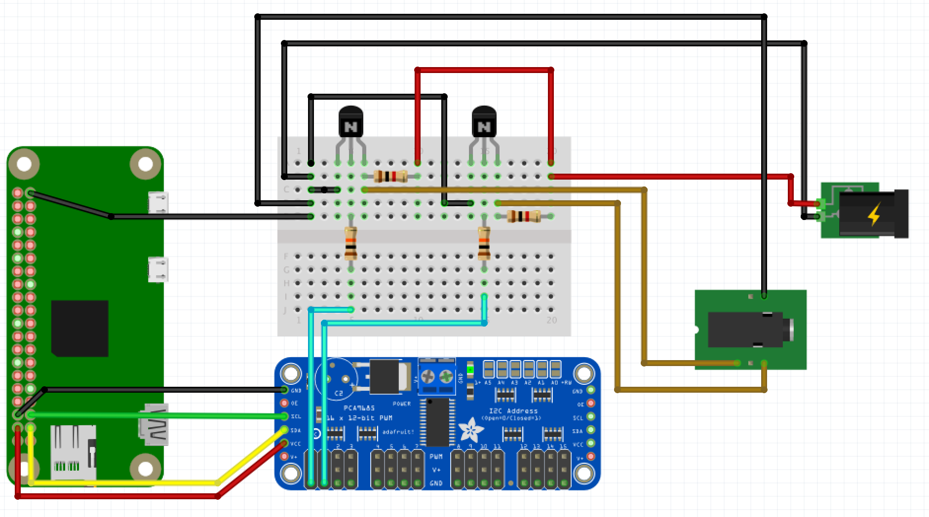
@Ryan115 I have a few more questions listed below in your diagram for reference. Thanks for being patient with me!!!
3.5mm stereo cable should have 3 connections. They are known as TRS (tip, ring, sleeve). You can also get some with 4 connectors (TRRS). For cables, amazon or ebay most likely. For separate plugs (the male connector) and jacks (the female connector) you will find some in bulk on both amazon and ebay, or you can look on Digikey/Newark/Mouser/Allied Electronics.
No problem on the questions, that is what these forums are here for. Everyone was new at some point, some people forget that.
The PWM GND should just be able to connect to the GND on the PCA9685 which should be connected to the pi GND.
V- DIM and GND should be the same, can you confirm that on your driver. I doubt that they are isolated.
You should not need to cut the wires that you have now. Can you post a picture of the connector side of the dimming module that you have?
Also, did you check the output of VDM+ to VDM- on the Hz and Duty settings of your multimeter. This should show whether that module is outputting pwm of analog. PWM can "trick" the VDC setting on most multimeters.