reef-pi :: An opensource reef tank controller based on Raspberry Pi.

Schreiber

Leviathan
View Badges
Joined
Jun 28, 2016
Messages
468
Reaction score
593
Location
Knoxville
Rating - 0%
0   0   0
Do you know the current draw from each of pca9685 pin? I would be very concerned if you are not powering it with dedicated 5v line.

I may be wrong, but isn't the current draw limited to only 25 mA from each pca9685 pin? From the datasheet: The PCA9685 operates with a supply voltage range of 2.3 V to 5.5 V and the inputs and outputs are 5.5 V tolerant. LEDs can be directly connected to the LED output (up to 25 mA, 5.5 V) or controlled with external drivers and a minimum amount of discrete components for larger current or higher voltage LEDs.
 

Schreiber

Leviathan
View Badges
Joined
Jun 28, 2016
Messages
468
Reaction score
593
Location
Knoxville
Rating - 0%
0   0   0
On the topic of PCA9685... I can use the PWM output from the PCA for the L293d Enable, correct? That would free up a couple of GPIO pins for me if that's the case.
 
OP
OP
Ranjib

Ranjib

7500 Club Member
View Badges
Joined
Apr 16, 2016
Messages
9,843
Reaction score
17,056
Location
Pleasant Hill, Concord
Rating - 0%
0   0   0
I may be wrong, but isn't the current draw limited to only 25 mA from each pca9685 pin? From the datasheet: The PCA9685 operates with a supply voltage range of 2.3 V to 5.5 V and the inputs and outputs are 5.5 V tolerant. LEDs can be directly connected to the LED output (up to 25 mA, 5.5 V) or controlled with external drivers and a minimum amount of discrete components for larger current or higher voltage LEDs.

Yes. But it’s also recommended to solder an appropriate capacitor in the place holder. This still requires you to pass enough power. If you are powering it from pi itself, that will limit the input power.
 

burningbaal

Active Member
View Badges
Joined
Aug 13, 2019
Messages
232
Reaction score
257
Location
Near Seattle
Rating - 0%
0   0   0
any reason teamviewer isn't viable for remote access to the pi? Just received/setup my canakit last night (rpi4 with 2GB), getting Ranthellion's hat, SRP8, etc today (I hope) and get some power control!
I'll look for a temp probe next, then look to incorporate my ATO, hoping to use the parts from my ebay ATO, so I'll need to figure out how to connect those sensors...
 

Halo_003

Community Member
View Badges
Joined
Apr 13, 2016
Messages
99
Reaction score
75
Rating - 0%
0   0   0
Hey guys,

I’m working with a really slim fixture for my LED build and realized my BlueFish Mini is too tall to fit under the splash shield. Would a Raspberry Pi Zero W be able to drive 4 PWM channels without any extra hardware? Would it need the ReefPi software installed to do so? The drivers are BlueAcro MicroDriver v1 and v2s.

edit: one more question, do any of you use a ReefPi only to control lights?
 
Last edited:

AbjectMaelstroM

Valuable Member
View Badges
Joined
Jul 21, 2019
Messages
1,527
Reaction score
1,810
Location
RVA
Rating - 100%
1   0   0
Hey guys,

I’m working with a really slim fixture for my LED build and realized my BlueFish Mini is too tall to fit under the splash shield. Would a Raspberry Pi Zero W be able to drive 4 PWM channels without any extra hardware? Would it need the ReefPi software installed to do so? The drivers are BlueAcro MicroDriver v1 and v2s.

4 individual channels? No, as I believe pi only has 2 of its own pwm pins. However you could tie in multiple channels to one pin, but as I said you could only control 2 independently of each other. If that makes sense.
 

MikeSpike

Community Member
View Badges
Joined
Jan 2, 2019
Messages
73
Reaction score
52
Rating - 0%
0   0   0
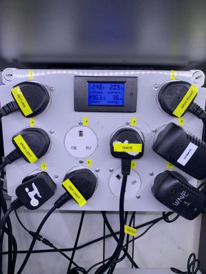
After fully testing my reef pi power controller I installed it into my tank cupboard. However for some reason now some of the relays don’t go ‘off’ ??? I can move the switch of on the equipment tab but the actual plug stays live? Is this a dodgy relay?? Any suggestions appreciated.

image.jpg
 

Urtoo

Well-Known Member
View Badges
Joined
Jul 1, 2019
Messages
688
Reaction score
924
Rating - 0%
0   0   0
Mike, did you bench test it and shown to be good? Did the relay board shift and pop a few wires? When moving, is it laying down or did you mount it on a bulkhead/wall? If that was mine, I would pull it down and make sure my standoffs and screw terminate are tight.
 
OP
OP
Ranjib

Ranjib

7500 Club Member
View Badges
Joined
Apr 16, 2016
Messages
9,843
Reaction score
17,056
Location
Pleasant Hill, Concord
Rating - 0%
0   0   0
Have checked. All the jumper wires still in place....
When you switch on the equipment/outlet from reef-pi, check if you see 3.3V output from the corresponding GPIO pin. If so, then reef-pi is fine, its likely the circuit or relay itself. You can then track down that voltage from GPIO to your relay input.. to find out if its the connection in between or the relay itself thats bad
 

MikeSpike

Community Member
View Badges
Joined
Jan 2, 2019
Messages
73
Reaction score
52
Rating - 0%
0   0   0
The relays are all fed of an independent 5V power source. Most of them work fine it’s just 2 of them. They do make a clicking sound when I turn them off but not as loud as the clicking sound made by the other relays that actually work
 

rushbattle

Valuable Member
View Badges
Joined
Oct 19, 2016
Messages
1,347
Reaction score
1,644
Location
Equality
Rating - 0%
0   0   0
The relays are all fed of an independent 5V power source. Most of them work fine it’s just 2 of them. They do make a clicking sound when I turn them off but not as loud as the clicking sound made by the other relays that actually work
Is there anything plugged into the outlets?
 

Halo_003

Community Member
View Badges
Joined
Apr 13, 2016
Messages
99
Reaction score
75
Rating - 0%
0   0   0
4 individual channels? No, as I believe pi only has 2 of its own pwm pins. However you could tie in multiple channels to one pin, but as I said you could only control 2 independently of each other. If that makes sense.

Thanks for the insight! One thing I came across was this: https://raspberrypi.stackexchange.c...i-use-the-gpio-for-pulse-width-modulation-pwm

Would software PWM over GPIO work for this? If so that would be cool, if not I think I could directly solder to a PCA9685 since the pins would probably be too tall.
 
OP
OP
Ranjib

Ranjib

7500 Club Member
View Badges
Joined
Apr 16, 2016
Messages
9,843
Reaction score
17,056
Location
Pleasant Hill, Concord
Rating - 0%
0   0   0

BenB

Community Member
View Badges
Joined
Jun 11, 2019
Messages
98
Reaction score
152
Rating - 0%
0   0   0
After fully testing my reef pi power controller I installed it into my tank cupboard. However for some reason now some of the relays don’t go ‘off’ ??? I can move the switch of on the equipment tab but the actual plug stays live? Is this a dodgy relay?? Any suggestions appreciated.

image.jpg

I Like the display with the power consumption values, how did you do that? You have a link where is explained how to make that???
 

Halo_003

Community Member
View Badges
Joined
Apr 13, 2016
Messages
99
Reaction score
75
Rating - 0%
0   0   0
For controlling outlet? Pi has two hardawre pwm pins that you can use with reef-pi without pca9685. We generally use it for lights

This is probably an ignorant question so bear with me. Is there a reason we can’t use software PWM on the other GPIO pins to drive the light channels?
 

Being sticky and staying connected: Have you used any reef-safe glue?

  • I have used reef safe glue.

    Votes: 95 88.0%
  • I haven’t used reef safe glue, but plan to in the future.

    Votes: 6 5.6%
  • I have no interest in using reef safe glue.

    Votes: 4 3.7%
  • Other.

    Votes: 3 2.8%
Back
Top