reef-pi :: An opensource reef tank controller based on Raspberry Pi.

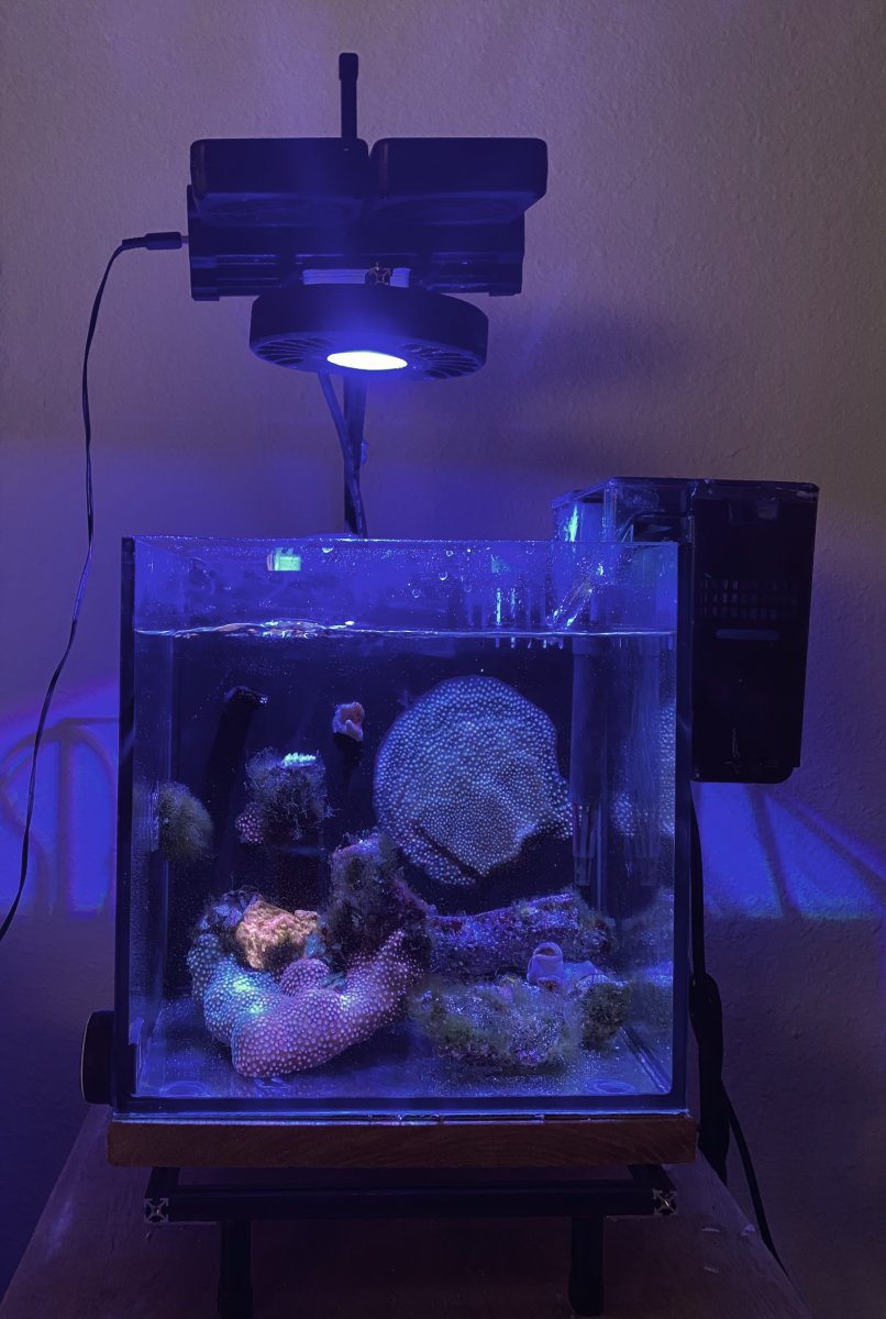
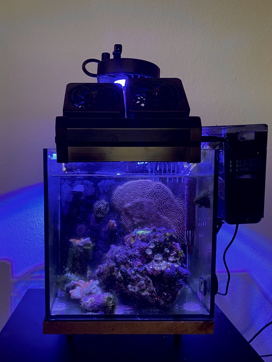
that was a long long time agoe :) . I changed the aquarium with something that does not have beveled corners. I use makerbeam to build a tank fixture that supports the light
Here is how they look now.
EF5FA51D-C17D-4134-A539-06158DD173FB.jpeg


close up pico 1
88D9AE5E-304F-47BE-B67A-6A8FADEE4DD2.jpeg

Close up pico 2
2F915A4E-437F-4BDA-BACB-1C3AE403B7BC.jpeg
Hey man, get rid of the aquaclear and get the tidals, much better then aquaclear filters and cost just a hair more.
 
Hi everyone, firstly I would like to say thank you to @Ranjib for creating reef-pi and to @robsworld78 for his excellent Robo-Tank controller.

I want to give a sneak peak of a touchscreen interface that I have developed for reef-pi, which is currently running on a 5" Waveshare hdmi touchscreen attached to my Raspberry Pi 4:
1627380987944.png

1627380995443.png
1627381004341.png
1627381013416.png

1627381312393.png


The interface is written in Python and Kivy. The software can write directly to the display without needing to run X Windows, which keeps the system requirements low. I am currently polishing up the code and will then release it on GitHub.

I will be posting more details about the hardware used and the 3d printed parts on my build thread:

Happy reef-pi-ing!

 
Hi everyone, firstly I would like to say thank you to @Ranjib for creating reef-pi and to @robsworld78 for his excellent Robo-Tank controller.

I want to give a sneak peak of a touchscreen interface that I have developed for reef-pi, which is currently running on a 5" Waveshare hdmi touchscreen attached to my Raspberry Pi 4:
1627380987944.png

1627380995443.png
1627381004341.png
1627381013416.png

1627381312393.png


The interface is written in Python and Kivy. The software can write directly to the display without needing to run X Windows, which keeps the system requirements low. I am currently polishing up the code and will then release it on GitHub.

I will be posting more details about the hardware used and the 3d printed parts on my build thread:

Happy reef-pi-ing!
Whoa,, this is super cool, thank you so much for sharing :-)
 
Hi everyone, firstly I would like to say thank you to @Ranjib for creating reef-pi and to @robsworld78 for his excellent Robo-Tank controller.

I want to give a sneak peak of a touchscreen interface that I have developed for reef-pi, which is currently running on a 5" Waveshare hdmi touchscreen attached to my Raspberry Pi 4:
1627380987944.png

1627380995443.png
1627381004341.png
1627381013416.png

1627381312393.png


The interface is written in Python and Kivy. The software can write directly to the display without needing to run X Windows, which keeps the system requirements low. I am currently polishing up the code and will then release it on GitHub.

I will be posting more details about the hardware used and the 3d printed parts on my build thread:

Happy reef-pi-ing!

That's awesome!!!

Do you have any issues using the touchscreen? I used to have a tablet by my tank I used to interact with Reef-Pi. But I found when I was using it the most, it was because I was working with my tank & my hands would tend to be wet. A quick wipe with a towel is enough to use a mouse, but even the slightest moisture on my fingers caused my tablet touchscreen to wig out.
 
I would also recommend just unplugging all wires and test the pwm pins in isolation, it’s rare for the pi to go bad like that
First, thanks for the help thus far, sadly the issue persists...
Steps I've taken:
Reloaded the Pi with minus one release, same for reef-pi (v4.0 vs 4.1)
Double-checked all wiring and voltages etc.
Looked in /sys/class/pwm and noticed that while files are there, the error shown appears when trying to view any of the txt files.

I also updated my image with labels if that helps.

Also included is a pic of the voltage from pi-ground to PWM for both ch0 and ch1, the voltage remained the same regardless of where I moved the slider in reef-pi.
 

Attachments

  • 2021-07-27_18-14-32.jpg
    2021-07-27_18-14-32.jpg
    152.7 KB · Views: 86
  • Labeled.jpg
    Labeled.jpg
    248.3 KB · Views: 86
  • PWMV.jpg
    PWMV.jpg
    77 KB · Views: 89
First, thanks for the help thus far, sadly the issue persists...
Steps I've taken:
Reloaded the Pi with minus one release, same for reef-pi (v4.0 vs 4.1)
Double-checked all wiring and voltages etc.
Looked in /sys/class/pwm and noticed that while files are there, the error shown appears when trying to view any of the txt files.

I also updated my image with labels if that helps.

Also included is a pic of the voltage from pi-ground to PWM for both ch0 and ch1, the voltage remained the same regardless of where I moved the slider in reef-pi.
You can not open the file like that. It’s a sysfs thing . You can only cat it. Run cat /path/to/file from your terminal , similar to how you are looking at the log
 
You can not open the file like that. It’s a sysfs thing . You can only cat it. Run cat /path/to/file from your terminal , similar to how you are looking at the log
Got it, attached is a screenshot of the cat command on those directories and my config.txt
 

Attachments

  • 2021-07-27_20-50-02.jpg
    2021-07-27_20-50-02.jpg
    163.7 KB · Views: 84
Hi everyone, firstly I would like to say thank you to @Ranjib for creating reef-pi and to @robsworld78 for his excellent Robo-Tank controller.

I want to give a sneak peak of a touchscreen interface that I have developed for reef-pi, which is currently running on a 5" Waveshare hdmi touchscreen attached to my Raspberry Pi 4:
1627380987944.png

1627380995443.png
1627381004341.png
1627381013416.png

1627381312393.png


The interface is written in Python and Kivy. The software can write directly to the display without needing to run X Windows, which keeps the system requirements low. I am currently polishing up the code and will then release it on GitHub.

I will be posting more details about the hardware used and the 3d printed parts on my build thread:

Happy reef-pi-ing!
Wow very nice, I love that red background and very cool what you did with reef-pi, it has no limits, great job!
 
Got it, attached is a screenshot of the cat command on those directories and my config.txt
This is the unevent values , I don’t need this one I was looking for the. pwm0/duty_cycle and pwm0/period . There should be one for each channel (pwm0 and pwm1)
You have tested the pi gpio pin in isolation right ?
 
That's awesome!!!

Do you have any issues using the touchscreen? I used to have a tablet by my tank I used to interact with Reef-Pi. But I found when I was using it the most, it was because I was working with my tank & my hands would tend to be wet. A quick wipe with a towel is enough to use a mouse, but even the slightest moisture on my fingers caused my tablet touchscreen to wig out.
Thanks Schreiber! Btw, I also have one of your leviathan boards, which I plan to put into service on another tank at some point...

I am using a resistive touchscreen (most of the small cheap touchscreens are resistive) which handles wet fingers better than capacitive displays. It also came with a small stylus which is useful in these situations. My goal was to deal with exactly the scenario you describe – when I am working on my tank I often need to turn off my skimmer or trigger a water change macro and it is a pain to have to pull out my phone and try to get the finger print sensor to recognise my moist fingers.

This is the touchscreen I am using:
 
I love these icons so much. I hope we can draw some inspiration on the main web ui. We have icon library already integrated, we have to do the work for assigning and showing the approriate icons in proper views (mobile , tablet etc ) . The form factor for the touch screen or mechanical buttons have no match
 
This is the unevent values , I don’t need this one I was looking for the. pwm0/duty_cycle and pwm0/period . There should be one for each channel (pwm0 and pwm1)
You have tested the pi gpio pin in isolation right ?
Pardon my ignorance, an absolute novice here. Yes, I even tried bridging in the old controller board (ie only using the Pi's PWM output to the light's PWM input. Attached is the cat for the two channels at 100 and at 10%.

2021-07-28_19-21-08.jpg
 
This is the unevent values , I don’t need this one I was looking for the. pwm0/duty_cycle and pwm0/period . There should be one for each channel (pwm0 and pwm1)
You have tested the pi gpio pin in isolation right ?
Ok quick update, having the right tools makes a world of a difference. I picked up a cheap o-scope and found the culprit, the viparspectra controller is running at a different frequency than the pi. The new question is how do I make the pi match the original controller?
 

Attachments

  • FromPi.jpg
    FromPi.jpg
    117.3 KB · Views: 71
Pardon my ignorance, an absolute novice here. Yes, I even tried bridging in the old controller board (ie only using the Pi's PWM output to the light's PWM input. Attached is the cat for the two channels at 100 and at 10%.

2021-07-28_19-21-08.jpg
Ok , so the pi pwm is working as expected, at least the linux sysfs side of thing is fine. You checked the pw output in isolation? like with scope or multi meter? Also, can you please start a separate thread.? lets leave this main thread for general discussion
 
I love these icons so much. I hope we can draw some inspiration on the main web ui. We have icon library already integrated, we have to do the work for assigning and showing the approriate icons in proper views (mobile , tablet etc ) . The form factor for the touch screen or mechanical buttons have no match
The icons are actually the Google Material Icons, which are open sourced under the Apache 2.0 licence. There are a huge number available:

The font is Orbitron, which is licenced under the Open Font License:
 
I am finishing up wiring my reef-pi build. I am going to build a 700 watt display light with 6 channels using meanwell hlg/elg dimmable to off drivers(0-10vdc, 10vPMW, or resistance). I would like to add the wiring to a plug for later use now for the control wires. I have an ML hat with 3v3 PWM signal via pca9685. Seems like the easiest way to control the 6 power supplies is by building the npn amplifier circuit in the guide. One question related to that is the power supplies are controlled by 100hz-3khz PMW signal, that frequency is achievable? Second question is do I need 12 control wires running to the light or 7 or 6 and use the mains ground used to power supplies frames as ? I'm trying to limit a gaudy mess of wires going to my light. Maybe I could keep the power supplies in the stand and just run one cable with the DC output from the power supplies. In that case can I use a shared ground wire for all 6 channels? Last question is more for a different thread so answer if u can. My reef-pi build thread: https://www.reef2reef.com/threads/matts-reef-pi-build-thread.745599/
 
Last edited:
I am finishing up wiring my reef-pi build. I am going to build a 700 watt display light with 6 channels using meanwell hlg/elg dimmable to off drivers(0-10vdc, 10vPMW, or resistance). I would like to add the wiring to a plug for later use now for the control wires. I have an ML hat with 3v3 PWM signal via pca9685. Seems like the easiest way to control the 6 power supplies is by building the npn amplifier circuit in the guide. One question related to that is the power supplies are controlled by 100hz-3khz PMW signal, that frequency is achievable? Second question is do I need 12 control wires running to the light or 7 or 6 and use the mains ground used to power supplies frames as ? I'm trying to limit a gaudy mess of wires going to my light. Maybe I could keep the power supplies in the stand and just run one cable with the DC output from the power supplies. In that case can I use a shared ground wire for all 6 channels? Last question is more for a different thread so answer if u can. My reef-pi build thread: https://www.reef2reef.com/threads/matts-reef-pi-build-thread.745599/
Pca9685 is 1.5khz so you should be good. I was thinking , may be use hdmi female breakout board for the control wires . Amazon product ASIN B07CBV8K2Y
 
Pca9685 is 1.5khz so you should be good. I was thinking , may be use hdmi female breakout board for the control wires . Amazon product ASIN B07CBV8K2Y
I have tried to solder connectors to hdmi wires but they're much to fragile for that. I'll look into that thanks.
 
I have tried to solder connectors to hdmi wires but they're much to fragile for that. I'll look into that thanks.
These are break out boards , so you just have to solder Male header pins and then you can directly use jumper wires on both ends
 
Hi, New to this forum - so firstly thanks for all the hard work on Reef pi, it's amazing.
I have a paludarium that I am using reef pi on Robo tank to control. I have a SHT31d that is measuring air temp and humidity. I would like to control some air circulation fans (12v) based on the humidity, but only have the control run during the day (at night the temp drops and relative humidity rises, so don't want to bring more cold air from the room into the tank). I can't figure out any way to do this. Does anyone have any suggestions?
unnamed.jpg
 

Attachments

  • 20210724-1824.jpg
    20210724-1824.jpg
    143.6 KB · Views: 76
  • 20210724-1832.jpg
    20210724-1832.jpg
    167.5 KB · Views: 82

TOP 10 Trending Threads

ARE YOU READY TO CONFESS TO CRAZIEST, DUMBEST, FUNNIEST THING YOU’VE EVER DONE IN REEFING?

  • Yeah, I'll confess! (Share your story in the comments!)

    Votes: 26 57.8%
  • Nah, I'll keep mine a secret...(Don't be like that, share with the class!)

    Votes: 19 42.2%
Back
Top
Home
Post thread…
Market
What's new