Looks good. How are you running the light schedule? It’s hard to tell in the pics. But is there room in there to put the relays inside the light itself?
Navigation
Install the app
How to install the app on iOS
Follow along with the video below to see how to install our site as a web app on your home screen.
Note: This feature may not be available in some browsers.
More options
You are using an out of date browser. It may not display this or other websites correctly.
You should upgrade or use an alternative browser.
You should upgrade or use an alternative browser.
Reef Pi Build
- Thread starter Diamond1
- Start date
- Tagged users None
Looks good. How are you running the light schedule? It’s hard to tell in the pics. But is there room in there to put the relays inside the light itself?
I'm still working on the actual circuit for the pi hat so I haven't messed with the programing yet. I will be testing with the relays today before I finalize the circuit and see what I come up with for a lighting schedule.
There is no room for the relays inside the fixture they made it very tight inside, so I will be putting the relays in the main box with the pi.
I'm also waiting on the board and parts for Wykat's pi hat so things are going to be changing across the board for the whole build.
One of these days I may build another one with the @wykat HAT also. But for now I will keep what I have been building. My reef-pi box is packed full right now. I have room for the PCA9865 and that’s about it. I am probably going to have to make a separate relay box. But I will see when my parts get here if I can fit everything. It would be nice if I can. And even nicer if a 3D printer finds its way under my tree 
i think quite a few of us are asking Santa for a 3D printer!One of these days I may build another one with the @wykat HAT also. But for now I will keep what I have been building. My reef-pi box is packed full right now. I have room for the PCA9865 and that’s about it. I am probably going to have to make a separate relay box. But I will see when my parts get here if I can fit everything. It would be nice if I can. And even nicer if a 3D printer finds its way under my tree
One of these days I may build another one with the @wykat HAT also. But for now I will keep what I have been building. My reef-pi box is packed full right now. I have room for the PCA9865 and that’s about it. I am probably going to have to make a separate relay box. But I will see when my parts get here if I can fit everything. It would be nice if I can. And even nicer if a 3D printer finds its way under my tree
I had been planning on an expansion of options since I started this I'm also going to be redoing my 14gallon cube and moving it next to my main display so the added options should allow me to run both tanks off 1 reef-pi and now seems as good a time as any.
I'm hoping for a cnc router under my tree, but I wouldn't be disappointed in a 3d printer either.
I wrapped some red tape on some of the white wires for a visual reference. The important thing is that everything in the circuit has been corrected and now I feel much better about the overall safety.

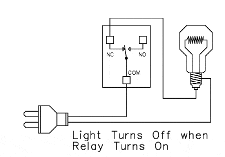
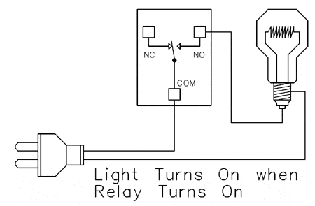
I was reading through this since I am doing my own relay wiring and am confused. What was the reasoning for connecting the outlets to the Comm on the relay vs connecting hot power to Comm and the outlets to either Normally open or Normally closed? Both will work but it seems backwards from everywhere else I have seen. I thought Comm on the relay gets the always on hot power which is shared on all relays, then you connect the outlets to either NO or NC depending on which way you want the relay to function.


It is my understanding that the common wire just runs from the common of the sockets to the common of the power supply and the hot wires are what needs to be switched so that if you have a short it doesn't feed back through the circuit.
My choice of wire colors may be confusing because of the white wires I use to daisy chain the positive wire to the relays (that's why they have red tap on them).
I have the relays set up like the bottom picture in you diagram with the hot wires going to the sockets from the normally off positions on the relays.
No other reason for doing it this way than it seemed logical to have them wired this way.
I suppose if you wire them in the normally closed position you would be putting less stress on the relays that stay on all the time.
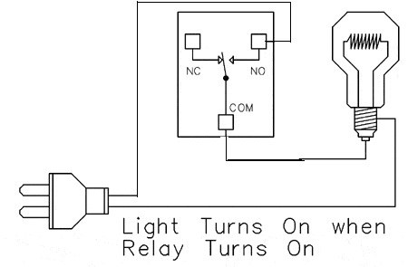
I am not an electrician so this is all new to me, its my first time ever messing with AC voltage. But looking at your pictures you have it wired like this

Which is backwards from all the other diagrams I have seen. I know @Erica-Renee had a reason for it but I didnt follow. Both ways will work as a switch and are switching the hot wire but does it matter which way its wired? I just want to make sure I do mine correct.
Half of my relays will be powered when off and the other half will be open when off.
It is my understanding that the common wire just runs from the common of the sockets to the common of the power supply and the hot wires are what needs to be switched so that if you have a short it doesn't feed back through the circuit.
My choice of wire colors may be confusing because of the white wires I use to daisy chain the positive wire to the relays (that's why they have red tap on them).
I have the relays set up like the bottom picture in you diagram with the hot wires going to the sockets from the normally off positions on the relays.
No other reason for doing it this way than it seemed logical to have them wired this way.
I suppose if you wire them in the normally closed position you would be putting less stress on the relays that stay on all the time.
I am not an electrician so this is all new to me, its my first time ever messing with AC voltage. But looking at your pictures you have it wired like this

Which is backwards from all the other diagrams I have seen. I know @Erica-Renee had a reason for it but I didnt follow. Both ways will work as a switch and are switching the hot wire but does it matter which way its wired? I just want to make sure I do mine correct.
Half of my relays will be powered when off and the other half will be open when off.
Normally your input 120v would go to comm and your load output either to the NC or NO. The mechanical relay is just a contact pad to one or the other NC or NO, it doesn't care which way the electricity flows. Generally, following standards for wiring and colors, etc. give a greater margin of safety to anyone else working on the circuit in the future.
I am not an electrician so this is all new to me, its my first time ever messing with AC voltage. But looking at your pictures you have it wired like this

Which is backwards from all the other diagrams I have seen. I know @Erica-Renee had a reason for it but I didnt follow. Both ways will work as a switch and are switching the hot wire but does it matter which way its wired? I just want to make sure I do mine correct.
Half of my relays will be powered when off and the other half will be open when off.
I wire mine normally closed ( power moving thru relay with pi turned off ) For things like Return pumps Heaters and other Critical systems that you do not want to be turned off if reef-pi has a issue.. things like skimmer ATO and dosing pumps your probably would rather them not run or work if your pi goes down..
As far as less or more stress on the relay . Well I will have to think about that...
Hope this helps explain my Reasoning . Rather its right or not its how I decided..
Ok I hope this clears it up a bit.
The way I have my relays is the positive wire comes into the relay at the comm terminal from the 120v power supply and are daisy chained across all terminals so each relay is getting a supply from the 120v input.
Each individual socket is wired to the Normally Open terminal (silver screws). When the relay is closed it allows the 120v current to energize the socket. All 8 of the relays are wired the same way.
The common wire is wired directly across all sockets (green screws) and goes to the common of the power supply.
The ground is wired across all sockets and connected to the ground from the power supply.
From everything I've seen and heard this is the correct way to wire the circuit. I chose not to use the normally closed side of the terminals since I run my return pump separate from reef-pi just in case of a rpi failure.
I know the color of the wires on the hot circuit should have been red or black and that has caused some confusion.
Certainly not trying to be argumentative, but I believe the center terminal is the common, at least every other relay board I have seen has the comm in center. So, NO-COMM-NC for each relay. Like I said earlier, the angry pixies don't care which way they go through the relay, you would only run into an issue if you tried to hook up to the NC terminal. There will never be a connection from NC to NO.Ok I hope this clears it up a bit.
The way I have my relays is the positive wire comes into the relay at the comm terminal from the 120v power supply and are daisy chained across all terminals so each relay is getting a supply from the 120v input.
Each individual socket is wired to the Normally Open terminal (silver screws). When the relay is closed it allows the 120v current to energize the socket. All 8 of the relays are wired the same way.
The common wire is wired directly across all sockets (green screws) and goes to the common of the power supply.
The ground is wired across all sockets and connected to the ground from the power supply.
From everything I've seen and heard this is the correct way to wire the circuit. I chose not to use the normally closed side of the terminals since I run my return pump separate from reef-pi just in case of a rpi failure.
I know the color of the wires on the hot circuit should have been red or black and that has caused some confusion.


Certainly not trying to be argumentative, but I believe the center terminal is the common, at least every other relay board I have seen has the comm in center. So, NO-COMM-NC for each relay. Like I said earlier, the angry pixies don't care which way they go through the relay, you would only run into an issue if you tried to hook up to the NC terminal. There will never be a connection from NC to NO.
That makes sense. Thanks for pointing it out. My thinking was correct but my application was off by thinking the NO terminal was the comm terminal.
Since this is all going to be torn down and redone by the 1st of the year I will redo this the right way.
This is awesome!! I have been wanting to build a reef pi since the beginning of the year. I was a little overwhelmed by the Linux programming aspect of it. I may just give it a shot now!
This is awesome!! I have been wanting to build a reef pi since the beginning of the year. I was a little overwhelmed by the Linux programming aspect of it. I may just give it a shot now!
Cool have fun with your build. Make a thread so that if you have any questions or run into problems you can get answers from the people in the know.
Wow!
I was just looking back at page #2 of this thread and realized that other than my dyslexic use of wire colors the first wiring attempt was correct.


Thanks for taking the time to take pics and document. Like I said I am very new to AC wiring and thats why I was so confused, it looked right the first time. I wouldnt say it was wrong so to speak just not standard like @ScottBrew had said. But regardless your thread has been a huge help to my build. Thanks again.
Thanks for taking the time to take pics and document. Like I said I am very new to AC wiring and thats why I was so confused, it looked right the first time. I wouldnt say it was wrong so to speak just not standard like @ScottBrew had said. But regardless your thread has been a huge help to my build. Thanks again.
Your very welcome.
Like I said when I started this I'm a complete noob to all this stuff too so if by my mistakes or successes we can all learn something then so be it.
This is one more reason for me to want to redo the whole build.
Which temperature probe did you end up using? I feel like its not the one shown on the 1st page of the thread here. Something about them always going bad real quick so you changed it to something else? Or am i wrong?
Also I was going to get the Raspberry Pi 3 B+.
Also I was going to get the Raspberry Pi 3 B+.
Last edited:
Similar threads
- Replies
- 8
- Views
- 170


