Reef-PI_<PCB's>

theatrus

Valuable Member
View Badges
Joined
Mar 26, 2016
Messages
1,957
Reaction score
3,355
Location
Sacramento, CA area
Rating - 0%
0   0   0
Although not a solution for all of us, it would be cool to convert a 3D printer into a PCB printer and do our own boards. Maybe some of our members with the 3D printers can give this a go and make a video. Just a thought...

PCB milling machines exist, but the reality is you can't ever do more than 1 layer, or two with extreme pain, since the via process is not milling friendly (wires through holes, or those tiny rivers, etc are all a giant pain). PCB manufacture is best to outsource, especially as its gotten so low cost.
 

crusso1993

7500 Club Member
View Badges
Joined
Oct 21, 2018
Messages
8,671
Reaction score
44,649
Location
SW, FL, USA
Rating - 0%
0   0   0
This would be super cool to work out details through prototyping. It would allow rapid iterations for testing which would really speed development time. No idea on the cost though. It might still be cheaper to go with a very cheap PCB manufacturer knowing that they are prototypes and super high quality is not needed.

My personal vision is to end up with professionally manufactured PCBs populated by professional assemblers (with pick and place and reflow process for low cost) conformal coated for longevity. As noted above that will be challenging for connectors and cooling.

Considering the turnaround on the PCB's from the cheaper producers will be a week, at minimum, I cannot agree with you enough about the prototyping! Obviously, if the designer and the 3D printer are different people, they would have to work together very closely.

Or, for prototyping, it may make a lot of sense to go the "film/expose/etch" route with pre-sensitized boards like in the link below. Then, once everything is worked out, ordering quality boards from a reputable source. Just throwing some ideas out there...

https://www.jameco.com/z/21-334-GC-...per-Clad-Circuit-Board-4-x-6-Inch_616251.html
 

theatrus

Valuable Member
View Badges
Joined
Mar 26, 2016
Messages
1,957
Reaction score
3,355
Location
Sacramento, CA area
Rating - 0%
0   0   0
Considering the turnaround on the PCB's from the cheaper producers will be a week, at minimum, I cannot agree with you enough about the prototyping! Obviously, if the designer and the 3D printer are different people, they would have to work together very closely.

Or, for prototyping, it may make a lot of sense to go the "film/expose/etch" route with pre-sensitized boards like in the link below. Then, once everything is worked out, ordering quality boards from a reputable source. Just throwing some ideas out there...

https://www.jameco.com/z/21-334-GC-...per-Clad-Circuit-Board-4-x-6-Inch_616251.html

Still can't make vias or multi-layer boards, so its more or less useless for the prototype work I end up doing, but if it works for you then go for it :)
 

buddy.

Active Member
View Badges
Joined
May 16, 2018
Messages
291
Reaction score
617
Location
Australia
Rating - 0%
0   0   0
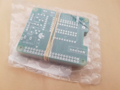
Got my boards :D
20181201_091551.jpg
 

rushbattle

Valuable Member
View Badges
Joined
Oct 19, 2016
Messages
1,347
Reaction score
1,644
Location
Equality
Rating - 0%
0   0   0
They look great, I'll probably solder the components this weekend and try it out. It took about 4 weeks for them to arrive.
@rushbattle
Nice! What solder are you using? I have done almost all of my soldering the last decade or so on hifi electronics, so we use quad eutectic solder. That wouldn't be a good idea for aquatic stuff. Also, what flux are you using in conjunction? Bad solder joints are miserable!
 

buddy.

Active Member
View Badges
Joined
May 16, 2018
Messages
291
Reaction score
617
Location
Australia
Rating - 0%
0   0   0
Nice! What solder are you using? I have done almost all of my soldering the last decade or so on hifi electronics, so we use quad eutectic solder. That wouldn't be a good idea for aquatic stuff. Also, what flux are you using in conjunction? Bad solder joints are miserable!
Actually I am not even sure haha. I have had the same roll of solder forever and used it for everything. It is probably just the roll with lead tin and flux in it.
I'll also be using the PWM board once it has been comfirmed that it is working.
 
OP
OP
W

wykat

Active Member
View Badges
Joined
May 23, 2018
Messages
182
Reaction score
421
Rating - 0%
0   0   0
They look great, I'll probably solder the components this weekend and try it out. It took about 4 weeks for them to arrive.
@rushbattle
Why did it take 4 weeks? I'm on the other side of the world and get them in 6-7 days.
Nevertheless it makes me happy to see the PCB's in my favorite countries, I've been there twice :), Sydney and East Coast. Driving left in Sydney during rush hour was my worst experience :D, apologies to the bus driver.
Paris is easier.
 
Last edited:

buddy.

Active Member
View Badges
Joined
May 16, 2018
Messages
291
Reaction score
617
Location
Australia
Rating - 0%
0   0   0
Why did it take 4 weeks? I'm on the other side of the world and get them in 6-7 days.
Nevertheless it makes me happy to see the PCB's in my favorite countries, I've been there twice :), Sydney and East Coast. Driving left in Sydney during rush hour was my worst experience :D, apologies to the bus driver.
Paris is easier.
I chose the cheapest shipping option as I was away on holiday (in the USA actually) so they were here waiting for me by the time I got home.
Driving for the first time on the right in LA peak hour was quite an experience back on my first visit to the states! Also it seems speed limits don't apply in California haha.
 

Ranjib

7500 Club Member
View Badges
Joined
Apr 16, 2016
Messages
9,843
Reaction score
17,058
Location
Pleasant Hill, Concord
Rating - 0%
0   0   0
So transistors arrived and new PWM module has been assembled :)
upload_2018-12-4_15-9-42.png

I2C is working and default address is 0x40 now :D

Will clean the board tomorrow and then start testing.
Nice work :) . You did the smd soldering as well?
 
OP
OP
W

wykat

Active Member
View Badges
Joined
May 23, 2018
Messages
182
Reaction score
421
Rating - 0%
0   0   0
Nice work :) . You did the smd soldering as well?
Yes I did the SMD soldering with all my vibration limitations as well :) Damaged 2 chips (not destroyed, but waiting for eye glasses to recover) were I bend the solder pins slightly. I've made pictures of every step I made, including problems and how to resolve them. The pictures helped me to see every potential problem before continuing.

Next step now is to verify functionality, then release a version on Github if everything is ok. There will be some minor improvements (Mainly silk screen and maybe moving some resistors to avoid height collision with Reef-PI_HAT DS18B20 connector), rest seems to be ok for now. Then I'll complete documentation:D
 

Ranjib

7500 Club Member
View Badges
Joined
Apr 16, 2016
Messages
9,843
Reaction score
17,058
Location
Pleasant Hill, Concord
Rating - 0%
0   0   0
Yes I did the SMD soldering with all my vibration limitations as well :) Damaged 2 chips (not destroyed, but waiting for eye glasses to recover) were I bend the solder pins slightly. I've made pictures of every step I made, including problems and how to resolve them. The pictures helped me to see every potential problem before continuing.

Next step now is to verify functionality, then release a version on Github if everything is ok. There will be some minor improvements (Mainly silk screen and maybe moving some resistors to avoid height collision with Reef-PI_HAT DS18B20 connector), rest seems to be ok for now. Then I'll complete documentation:D
and please put your name or github link on the silkscreen :) , you deserve the due recognition.
 

rushbattle

Valuable Member
View Badges
Joined
Oct 19, 2016
Messages
1,347
Reaction score
1,644
Location
Equality
Rating - 0%
0   0   0
So transistors arrived and new PWM module has been assembled :)
upload_2018-12-4_15-9-42.png

I2C is working and default address is 0x40 now :D

Will clean the board tomorrow and then start testing.
Like some of Ranjib and theatrus’s posts, I can’t like this post enough. Needs to be multiple likes allowed or something.

Thank you for making it compatible with theatrus HAT! That combo is going to be super awesome! I think it means I can skip buying bluefish mini for my two builds as well, which is really nice.
 
OP
OP
W

wykat

Active Member
View Badges
Joined
May 23, 2018
Messages
182
Reaction score
421
Rating - 0%
0   0   0
Put priority on Buddy.'s problem with the relay on the Reef-PI_HAT. It's better to solve problems before adding potential more ;)

The 'proposed' relay board in my documentation does work with the latest Reef-PI_HAT and I also discovered it also does work without GND connection, that's the biggest surprise to me. Now I understand the 9 pin solution (without GND) but still don't understand how it can work... :confused: I disconnected GND on my relay board and it still worked whereas the schematics require an NPN transistor to GND after the optical isolation. Where does the relay board get it's reference to GND when no GND is connected?

I have both schematics of proposed relay board and the one used by Buddy and they are completely different in the way they interface to the mechanical relay. Will take some time to understand the interface with the ULN2803
 

Creating a strong bulwark: Did you consider floor support for your reef tank?

  • I put a major focus on floor support.

    Votes: 60 38.5%
  • I put minimal focus on floor support.

    Votes: 35 22.4%
  • I put no focus on floor support.

    Votes: 55 35.3%
  • Other.

    Votes: 6 3.8%
Back
Top