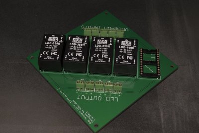
Reef-PI_<PCB's>

OP
OP
W

wykat

Active Member
View Badges
Joined
May 23, 2018
Messages
182
Reaction score
421
Rating - 0%
0   0   0
OP
OP
W

wykat

Active Member
View Badges
Joined
May 23, 2018
Messages
182
Reaction score
421
Rating - 0%
0   0   0
Reef-PI_PWM PCB files are now available on Github :)
https://github.com/vandegraaf/Reef-PI_PCBs

No changes between v0.3 and v1.0 have been made to the schematics but following to the PCB design:
1) Moved some resistors in order to avoid a conflict between the solder points and the DS18B20 interface below it on the Reef-PI_HAT PCBA
2) Solved (at least I hope so) a conflict between the edge-cut and drill files. PCBWAY.com always complained correctly about this (use drill file, then it's ok, no reason to have an edge-cut around the solder points)
3) Updated the silk screen
4) Moved the right corner (between all PWM output connectors) mounting hole 0.3mm down to fit correctly :p

The changes were more difficult as PCBWAY.com complained about a conflict between the layers edge-cut and drill file. Unfortunately Kicad doesn't have a feature in v5 to correct the edge-cut file for components so it took some time to sort out how to solve (at the end I edited the component file with a text editor to delete the conflict and had to reinstall all connectors with the new file in Kicad).

You can see the movement of some resistors in the picture below:
upload_2018-12-8_12-40-0.png
 

Ranjib

7500 Club Member
View Badges
Joined
Apr 16, 2016
Messages
9,843
Reaction score
17,056
Location
Pleasant Hill, Concord
Rating - 0%
0   0   0
Reef-PI_PWM PCB files are now available on Github :)
https://github.com/vandegraaf/Reef-PI_PCBs

No changes between v0.3 and v1.0 have been made to the schematics but following to the PCB design:
1) Moved some resistors in order to avoid a conflict between the solder points and the DS18B20 interface below it on the Reef-PI_HAT PCBA
2) Solved (at least I hope so) a conflict between the edge-cut and drill files. PCBWAY.com always complained correctly about this (use drill file, then it's ok, no reason to have an edge-cut around the solder points)
3) Updated the silk screen
4) Moved the right corner (between all PWM output connectors) mounting hole 0.3mm down to fit correctly :p

The changes were more difficult as PCBWAY.com complained about a conflict between the layers edge-cut and drill file. Unfortunately Kicad doesn't have a feature in v5 to correct the edge-cut file for components so it took some time to sort out how to solve (at the end I edited the component file with a text editor to delete the conflict and had to reinstall all connectors with the new file in Kicad).

You can see the movement of some resistors in the picture below:
upload_2018-12-8_12-40-0.png
Awesome :)
 
OP
OP
W

wykat

Active Member
View Badges
Joined
May 23, 2018
Messages
182
Reaction score
421
Rating - 0%
0   0   0
Ordered my pwm PCB's :D
I got a quote to assemble with just the SMD but it was stupidly expensive so I'll just have to hope I can do it myself!
Make sure you have solder wick! Don't be too concerned if you short cut some pins, they can easily be removed with solder wick. I think (not tried yet) best is to use a thicker solder tip both to not damage the board and to have a better heat transfer to the solder wick.
 

buddy.

Active Member
View Badges
Joined
May 16, 2018
Messages
291
Reaction score
617
Location
Australia
Rating - 0%
0   0   0
OP
OP
W

wykat

Active Member
View Badges
Joined
May 23, 2018
Messages
182
Reaction score
421
Rating - 0%
0   0   0
@wykat I am just ordering the components from a local supplier and I am having trouble finding a couple of them on the site. https://au.element14.com
https://www.mouser.com/ProductDetail/610-BC184B
Alternative: https://au.element14.com/on-semiconductor/bc33725bu/transistor-bipol-npn-45v-to-92/dp/2453781 (universal npn transistor with same CBE footprint according datasheet)

https://www.mouser.com/ProductDetail/80-MMK5104J50J01TR18
Alternative: https://au.element14.com/vishay/bfc237011104/cap-0-1-f-63v-10-pet/dp/1215508 (should fit dimensional)

https://www.mouser.com/ProductDetail/652-4607X-1LF-8.2K .........I am not sure if this will work?
Alternative: https://au.element14.com/bourns/4607x-101-472lf/res-n-w-bussed-4-7k-2-100v-sip/dp/2787743 (is just a pull up resistor, value not critical between 4K7 and 10K).

Is it also possible to just use pins instead of the audio jacks?
Yes, no problem, just don't reverse them as I don't know what's happening then.
 

buddy.

Active Member
View Badges
Joined
May 16, 2018
Messages
291
Reaction score
617
Location
Australia
Rating - 0%
0   0   0
Thanks!!

These are the drivers that I have been using for the last 5 years or so for my LEDs. I have been using a controller with only 4 channels though so I can't wait to have so much more control :D
drivers.jpg
 

Diamond1

Valuable Member
View Badges
Joined
Oct 17, 2013
Messages
1,368
Reaction score
1,911
Location
Cleveland Ohio
Rating - 0%
0   0   0
Just looking for clarification please. I'm not using the 1/8 inch jack, I want to hard wire a mini xlr to the board.

Is this correct?

Temp probe connections.png
 

Diamond1

Valuable Member
View Badges
Joined
Oct 17, 2013
Messages
1,368
Reaction score
1,911
Location
Cleveland Ohio
Rating - 0%
0   0   0
Great job on these boards @wykat.

Here's what mine looks like. Still need to solder the 2x20 header and the temp probe wires then I'll be testing this week.
I'm not a big fan of the push pin jumper wires or the 1/8" temp probe jacks so I direct wired the outputs from the ULN 2803s, dc motors and temp probe. They will all go to a set of terminal blocks so if I need to I can easily disconnect everything.

IMG_4619.JPG
 
OP
OP
W

wykat

Active Member
View Badges
Joined
May 23, 2018
Messages
182
Reaction score
421
Rating - 0%
0   0   0
Great job on these boards @wykat.

Here's what mine looks like. Still need to solder the 2x20 header and the temp probe wires then I'll be testing this week.
I'm not a big fan of the push pin jumper wires or the 1/8" temp probe jacks so I direct wired the outputs from the ULN 2803s, dc motors and temp probe. They will all go to a set of terminal blocks so if I need to I can easily disconnect everything.

IMG_4619.JPG
Happy to see people using these boards and yes as stated before tricky point are the connectors. Learning a lot from https://www.reef2reef.com/threads/devoted-reefer-250.263426/page-13 (still many pages to go). Will see if I can draw the principle of a modular housing tomorrow. Quite comfortable at the moment. Objective is a Red Sea Reefer 250 with 10cm/4inch distance to the wall behind to fit the Reef-PI_housing including cooling/water protection/wiring.
 
Last edited:

buddy.

Active Member
View Badges
Joined
May 16, 2018
Messages
291
Reaction score
617
Location
Australia
Rating - 0%
0   0   0
My PWM boards arrived today from PCBWAY :D I chose dhl this time for delivery so it was far quicker. My components should arrive sometime next week and I can test it out!
 
OP
OP
W

wykat

Active Member
View Badges
Joined
May 23, 2018
Messages
182
Reaction score
421
Rating - 0%
0   0   0
First sketch:
upload_2018-12-13_15-56-8.png

Just now 3D printing is running (chili's have to wait) to get a physical impression. Wanted to use Mini XLR connectors but that's not going to work (hex nut). Still looking to minimize overall size. Module should not only cool down the PWM module but also others. The PWM PCBA module would fit in the lower right corner, don't think connectors on the PWM module would be required, direct wires to female connectors.
 

BlakeFL

Community Member
View Badges
Joined
Dec 8, 2012
Messages
29
Reaction score
31
Rating - 0%
0   0   0
What software are you using to design? I'm thinking about getting an Ender 3 as a Christmas present to myself.
 
OP
OP
W

wykat

Active Member
View Badges
Joined
May 23, 2018
Messages
182
Reaction score
421
Rating - 0%
0   0   0
What software are you using to design? I'm thinking about getting an Ender 3 as a Christmas present to myself.
Started 3D design with sketchup, somehow can't get myself with FreeCAD but there are several alternatives. As printer I'm using an 'old' Malyan M150, almost wrote off this printer and build and almost finished a new dual head Tarantula, but since that was almost finished the Malyan is running fine 24/7 :D Don't touch a running system.

What I've learned is:
- Don't change, if not required between material (PLA, ABS, PETG, ...). It will constipate the nozzle due to different temperatures required.
- Use a glass plate (or Ikea mirror) with hair spray for sticking the first layers (basically I only use PETG at 100 degrees going down to 80 degrees after multiple layers)
- I run at a lower print speed, so that material drops can be 'recovered' by the hot needle during next runs (potentially a PETG issue)

The glass/hair spray is holding so good that I've even broken glass particles out of the glass plate, let it cool down below 40 degrees! you can hear when the printed parts are 'breaking' from the glass plate, then they can be taken off easily.
 

theatrus

Valuable Member
View Badges
Joined
Mar 26, 2016
Messages
1,951
Reaction score
3,353
Location
Sacramento, CA area
Rating - 0%
0   0   0
Started 3D design with sketchup, somehow can't get myself with FreeCAD but there are several alternatives. As printer I'm using an 'old' Malyan M150, almost wrote off this printer and build and almost finished a new dual head Tarantula, but since that was almost finished the Malyan is running fine 24/7 :D Don't touch a running system.

What I've learned is:
- Don't change, if not required between material (PLA, ABS, PETG, ...). It will constipate the nozzle due to different temperatures required.
- Use a glass plate (or Ikea mirror) with hair spray for sticking the first layers (basically I only use PETG at 100 degrees going down to 80 degrees after multiple layers)
- I run at a lower print speed, so that material drops can be 'recovered' by the hot needle during next runs (potentially a PETG issue)

The glass/hair spray is holding so good that I've even broken glass particles out of the glass plate, let it cool down below 40 degrees! you can hear when the printed parts are 'breaking' from the glass plate, then they can be taken off easily.

My PETG ends up a lot more stringy than ABS, so I've found needing to up retraction amounts a bit to reduce that. I haven't found the need for adhesive on a glass plate at 80C.
This is on an old Qidi Tech I (FlashForge clone) using Simplify3D as the slicer.
 
Back
Top