RFBF's Five Footer

OP
OP
redfishbluefish

redfishbluefish

Stay Positive, Stay Productive
View Badges
Joined
Mar 22, 2012
Messages
11,704
Reaction score
25,717
Location
Sayreville, NJ
Rating - 0%
0   0   0
Miscellaneous Stuff (continued]

V. Saltwater Mixing


It's amazing what you do when you first start on this saltwater venture, and you try to save money. My first mixing container was a Rubbermaid Roughneck storage container. When filled with water, the sides would buldge out.

IMG_2091.jpg


No problem....the water wasn't in there that long......until.....I was using the same container for storing towels out at the pool. After about three years, this container started to break apart. It became brittle and just fell apart. Granted, it was out in the sun, but I thought of the one I was using for water!

That's when I made the switch to Brute cans. First one was a 20 gallon to mix 15 gallons of new water....with a single Koralia K4.


At this point I was still using old salt buckets to hold the "dirty" water that was being removed. Every week I'd fill up three salt buckets with old water to do a water change:

IMG_5168.jpg


The weekly water changes just became too much. So I decided to do 25 gallons every two weeks. I couldn't do that in the 20 gallon Brute, so I picked up a 32 gallon Brute and add a Koralia K8 to help in mixing:


Using five salt buckets became old real fast for the old water, so I went out and picked up a second 32 gallon Brute. So one for making new water, and one for hauling away the old water.


In addition, I picked up the dollies. These things are great. I can wheel around the new water and wheel around the old water. A little pricey, but I'd suggest getting the dollies as well.

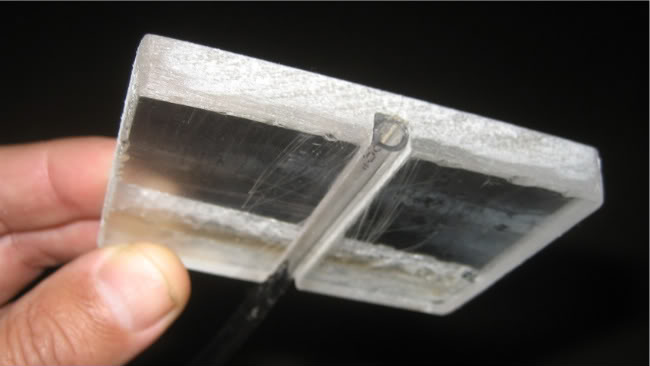
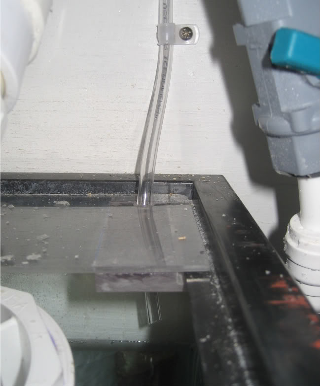
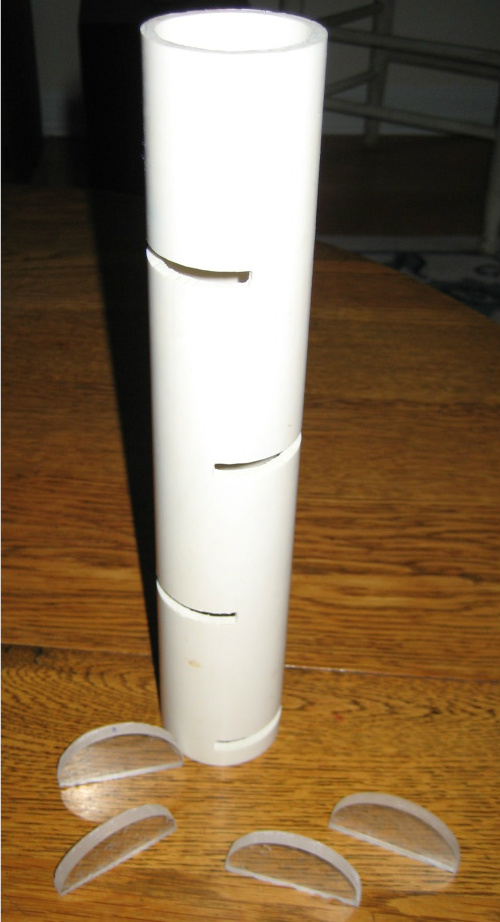
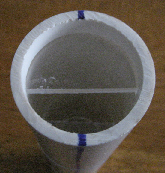
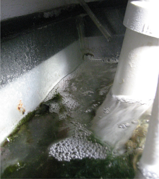
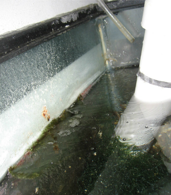
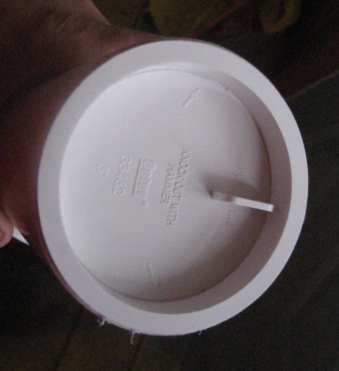
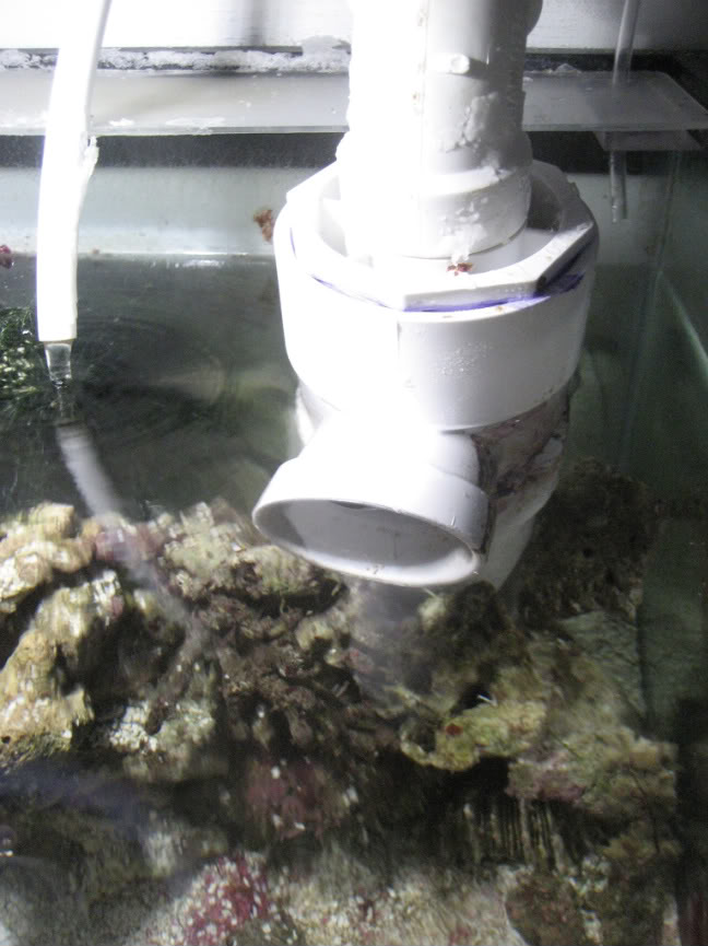
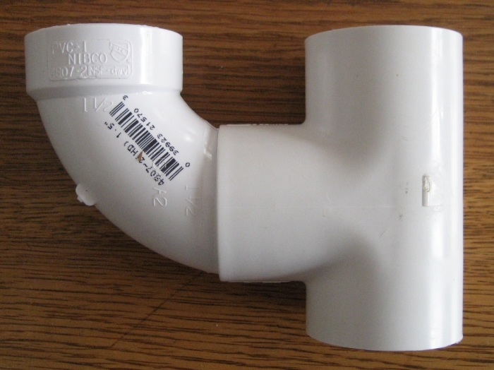
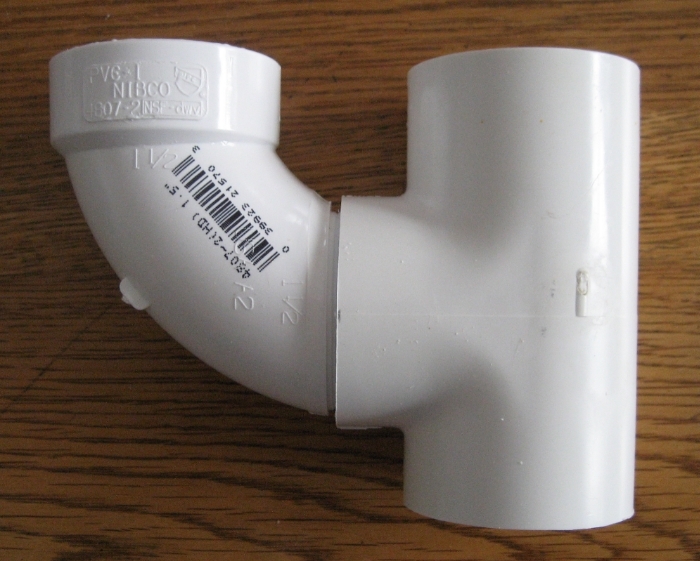
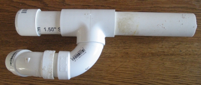
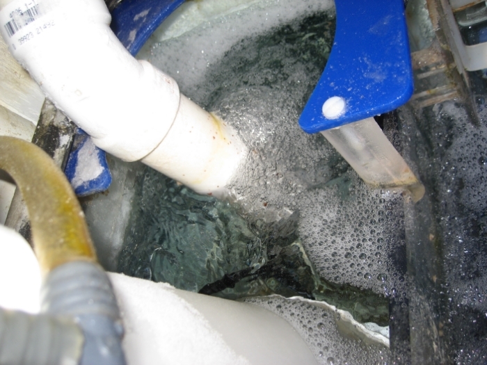
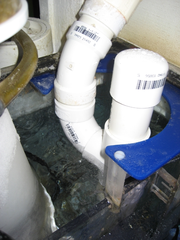
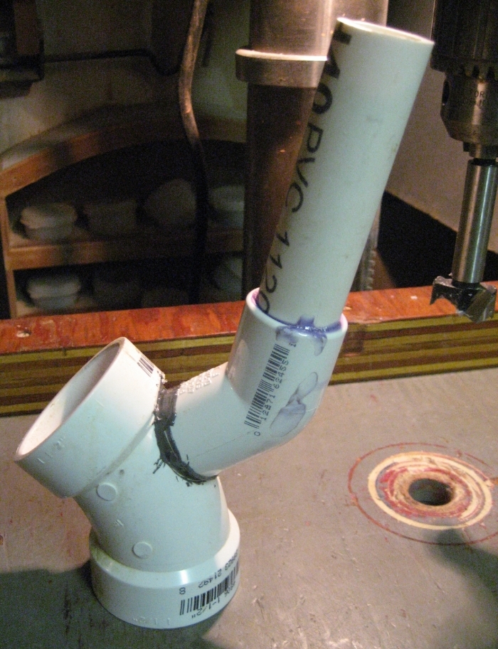
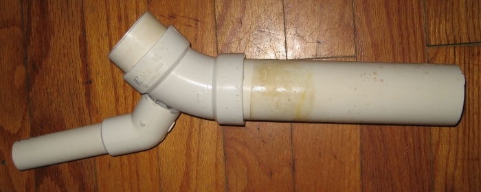
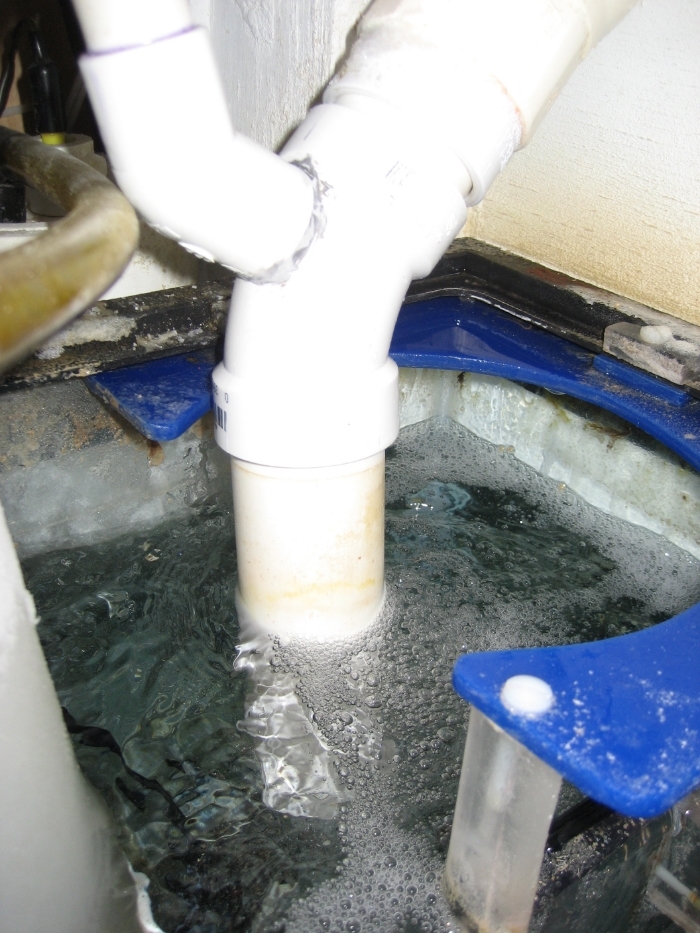
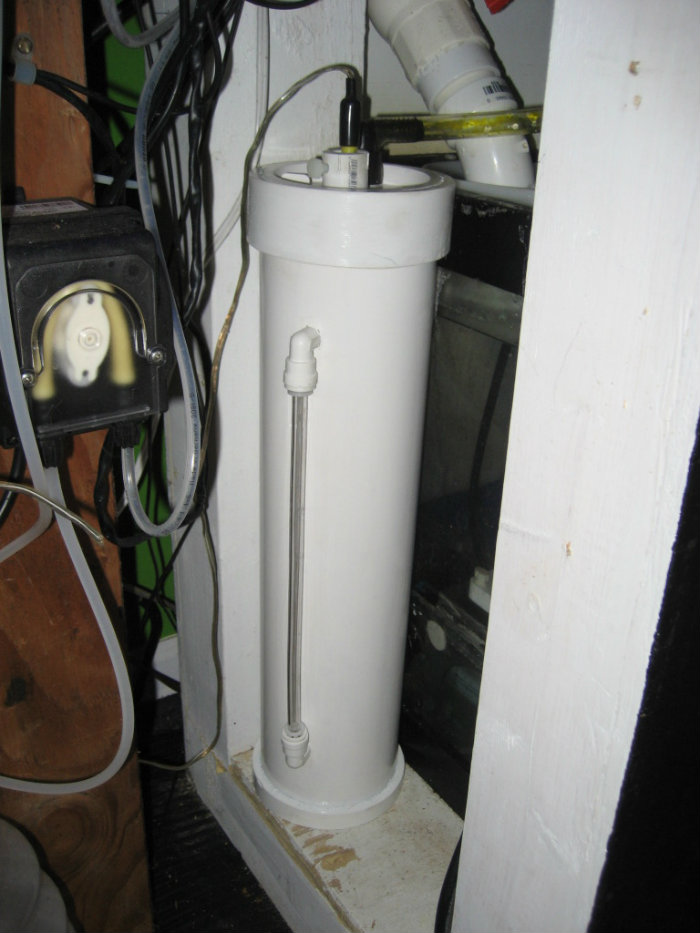
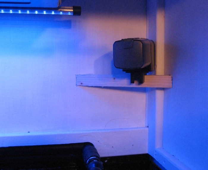
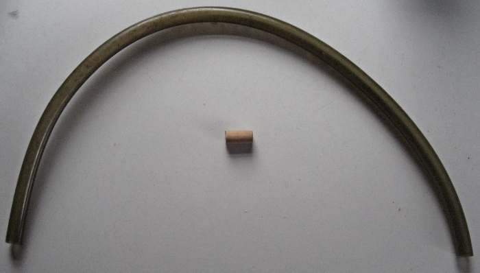
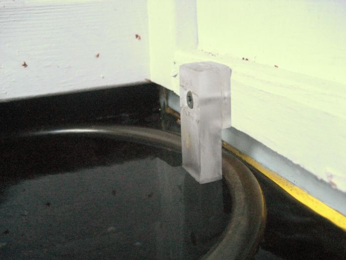
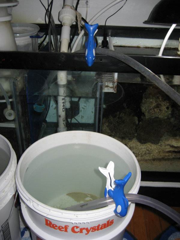
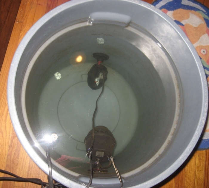
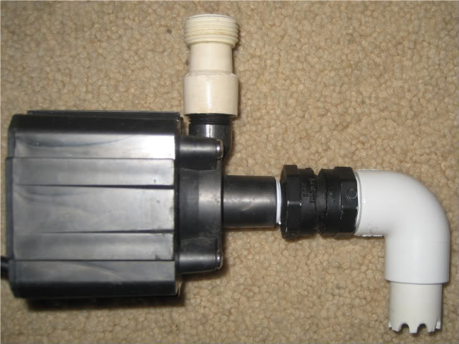
Finally, the water is pumped into the tank with a MAG7 with a DIY Rube Goldberg I put together to suck up the last drop, and a little adaptor to hook directly to a hose fitting.

 
OP
OP
redfishbluefish

redfishbluefish

Stay Positive, Stay Productive
View Badges
Joined
Mar 22, 2012
Messages
11,704
Reaction score
25,717
Location
Sayreville, NJ
Rating - 0%
0   0   0
Thanks @KorD for the kind words......and here's more!

Miscellaneous Stuff (continued]

VI. Canopy


When the tank was first set up with T5's, I made a temporary canopy out of reclaimed 1/4 inch plywood that simply slid down over the light setup. It was a pain to take off and put back on.

IMG_1628.jpg


Since I excel at procrastinating, I eventually added a couple trim pieces to this box and painted it black to match the stand.

IMG_2592.jpg


....still with the intent to build a proper canopy with doors.

Along came LED's, and a number of local folks put the fear of God in me about burning your corals, and the need to acclimate them to the new LEDs. I built a behemoth of extentions to this canopy and would lower the LEDs once a week.

IMG_4526.jpg


Eventually the canopy had to go as the light unit was being lowered. To keep fish from carpet surfing, I quickly made a box out of lumber in the basement, and took the screen off the back door, and stapled onto this frame.

IMG_4539.jpg


In December of 2012 I finally got around to building a proper canopy. Here's what I did. Instead of using 2 x 2’s, which are commonly used in canopies, I made “L” brackets out of inexpensive fir stripping. The primary reason is strength over five foot, but also for overall weight….these are lighter:

CanopyBrace.jpg


This “L” bracket is more stable than a five foot 2 x 2. I’ll use these on the two top braces of the canopy. The bottom braces are trimed fir strip, with the back piece having the cutout to fit around the return lines that come over the back of the tank

With these “L” brackets installed, here is the carcass of the canopy….using the end pieces from the original temporary canopy.

CanopyCarcass.jpg


On the front lower frame member I attached a strip of 1/16 acrylic, jutting down a half inch. This will hit the front glass of the tank and keep the canopy from sliding back.

CanopyFrontEdge.jpg


In retrospect, I should have notched this acrylic into that lower brace, because I now had to notch the door to fit over this piece of acrylic.

A piece of 1/4 inch plywood (from the original temporary canopy) was attached to the back, and this box was primed with Kilz….here it is upside down without the door:

CanopyPrimed.jpg


And here’s the door with the hinges set. This too was from the temporary canopy, with the lower edge notched to fit the acrylic.

CanopyDoor.jpg


And here is the finished canopy, door open:

CanopyOpen.jpg


And door closed:

CanopyDoorClosed.jpg
 
OP
OP
redfishbluefish

redfishbluefish

Stay Positive, Stay Productive
View Badges
Joined
Mar 22, 2012
Messages
11,704
Reaction score
25,717
Location
Sayreville, NJ
Rating - 0%
0   0   0
Miscellaneous Stuff (continued)

VII. Fans


When the tank was first set up, the T5's and tank were cooled by a desk fan we already had sitting around. It just happened to sort of fit in the end of the lights.

IMG_0074.jpg


This fan eventually died. I noticed this one day when walking past the fish room and the lights were not on. I had set the ReefKeeper to turn off the lights if the tank got hotter than 85. Sure enough, the fan was dead.

With the canopy idea floating around in my head, this purple beast wouldn't have worked anyway. So I built a fan holder out of scrap plexiglass, to hold 5 80mm fans that I salvaged from old computers sitting in the basement. If anything, it was a cause to finally pitch some of those first computers we purchased in the beginning of time....ran on DOS and had the large floppy discs...I think 5 1/2 inches.

IMG_0084.jpg


However, over the next year I watched as first one, then two, then three fans died....eventually down to only one fan running.

This was about the time the canopy was being made, and I picked up two $10 fans from WalMart. One went in the sump:

IMG_4180.jpg


and the other went into the canopy....simply zip-tied in:

IMG_4179.jpg


Both of these are attached to the Reefkeeper to turn on when the temperature approaches 79.

I did have these on the canopy with the LEDs, and they only came on in the summer when I didn't have the air conditioner on, on those hot days. Eventually they too died, and now I rely on having the air on in the fish room in the summer time. With the LED's, as long as the room is about 75, the tank is fine with temperature.
 
OP
OP
redfishbluefish

redfishbluefish

Stay Positive, Stay Productive
View Badges
Joined
Mar 22, 2012
Messages
11,704
Reaction score
25,717
Location
Sayreville, NJ
Rating - 0%
0   0   0
I'm taking a break from summarizing my build to talk about the issue I had yesterday with the wet side of my Vortech MP40. I came into the fish room and found the entire wet side spinning real fast. Had never seen that before. I put in the back-up wet side, and the impeller on that one wouldn't spin. Two MP40's! I had found that the integrity of the plastic surrounding the magnet was compromised, causing the magnet to rust and scale and swell up, binding against the casing, stopping the impeller. I believe this oxidation was accelerated with my recent bath I gave both these wet sides in bleach. I should point out that both these wet sides are from 2009.

I documented my horror HERE.

I should have seen this coming. About two weeks ago this wet side was slowly spinning.


I just assumed it was the rubber pad on the back that was wearing out, so I simply turned it down until it stopped spinning.

Little did I know.

I did put an old Koralia K4 in the tank to hold me over, but I didn't realize it was too high in the tank, and when I returned to the room, the floor had a couple gallons of water on it. I was having a marvelous day!!!!

So to hold me over until the new wet side gets here (on Friday), I took the magnet that had the plastic back pulled off and scraped off all the lose scale. Without using the plastic back, I put the wet side back together and put it in the tank. I must say, it's running extremely well. The dry side isn't as warm as it's been recently. I'm curious how much more scale I'll find when I pull this out on Friday after being exposed to saltwater.

I wasn't planning on spending $150 on two new wet sides, so to lessen the pain, I only ordered one.....for now. I'm also keeping an eye on the other 40 I have in the tank that is the same age, but did not get a bleach bath.
 
Last edited:
OP
OP
redfishbluefish

redfishbluefish

Stay Positive, Stay Productive
View Badges
Joined
Mar 22, 2012
Messages
11,704
Reaction score
25,717
Location
Sayreville, NJ
Rating - 0%
0   0   0
Back to summarizing my build:


Miscellaneous Stuff (continued)

VIII. ATO Reservoir


As probably most of us, when the tank was first set up, I manually topped it off everyday. It didn't take long to realize the benefit of and ATO. However, I struggled with the reservoir. I had room in the stand, but felt it would have been too difficult to refill this reservoir. My water is made in the basement by filling 5 gallon water jugs.

Here's what I came up with.....the water cooler concept reservoir....using a five gallon bucket from my pool, and a water jug. Simply cut a circle out of the top of the lid.

IMG_1690.jpg


To hold the tubing down at the bottom of the bucket, a scrap piece of acrylic was slotted to tightly hold the tubing.

IMG_1697.jpg


The bucket was painted black and the tubing was run into the stand. It's hard to see, but just below the window stool is the tubing

IMG_1706.jpg


The sump was fed through an AquaHub ATO and a Tom's Aqualifter. The black box contains the relay, with the Tom's Aqualifter off to the right.


IMG_1721.jpg


And here's where the tubing enters the sump

IMG_1700.jpg


Everything was just humming along, with water additions a breeze by simply dumping another water jug onto the top of the bucket......Until, the lid cracked

ATOReservoirTop.jpg


Hard to see in that above picture....here's a close-up

ATOReservoirCracked.jpg


By now I really liked this reservoir, so to fix this I made an acrylic donut out of 1/2 acrylic:

Reservoirdonuttop.jpg


Here it is on the lid:

Reservoirwithacrylictop.jpg


And what I did to secure the donut was to drill and tap the acrylic and attach the donut with nylon bolts.

ReservoirBoltedLidB.jpg


Eventually would like to hide this behind a three sided box, but I'm still thinking how I could do this and still see when it needs a new jug of water.
 
OP
OP
redfishbluefish

redfishbluefish

Stay Positive, Stay Productive
View Badges
Joined
Mar 22, 2012
Messages
11,704
Reaction score
25,717
Location
Sayreville, NJ
Rating - 0%
0   0   0
Thanks Kevin, that's kind of you.

One more thing on this reservoir....I noticed the height of the water when a full jug of water was added was above my sump level.......I had to scratch my head on this one.....where was the siphon point? After having to actually give it some thought, it is actually at the level of the water in the bucket. The water in the jug does not add to the water height as far as the siphon is concerned.
 
OP
OP
redfishbluefish

redfishbluefish

Stay Positive, Stay Productive
View Badges
Joined
Mar 22, 2012
Messages
11,704
Reaction score
25,717
Location
Sayreville, NJ
Rating - 0%
0   0   0
Present day update.

Woooo Hoooo! My new wetside arrived.

This new MP40 wetside is totally different than the older MP40, and is in fact just like the MP10 wetside.

Here are the guts of the older MP40 wetside....note every piece comes apart to an individual piece:


Here is the new MP40 wetside, where the impeller, plate and magnet are one (just like the MP10):


I was actually quite surprised to see grease used on the shaft.....and quite a bit of grease at that. When I first opened the box just after arriving, the impeller was very difficult to spin, with considerable amount of drag. After disassembling and seeing the grease, I'm pretty sure it was from the increased viscosity of the grease from sitting in cold trucks the last 3-4 days.:


The other difference with this shaft is that the metal center shaft extends all the up to, and into the cage piece. The old style shaft ended before the cage with a nut on the bolt/shaft.

A closer comparison and it would appear that the impellers/propellers are the same size and shape:


The one difference noted in the general design was the lack of that blocked area on the cage with the newer model:


Now to put this little puppy in the tank and watch it spin. I'll also purchase a second after observing this one for a month or so. It spreads the pain a little better that way.
 

Jimbo662

2500 Club Member
View Badges
Joined
Oct 1, 2013
Messages
4,745
Reaction score
2,144
Location
Austin, Tx
Rating - 0%
0   0   0
Is your name MacGyver??? I love the idea of the attachment for the pump that does the water changes. I'm going to have to steal that one!
 
OP
OP
redfishbluefish

redfishbluefish

Stay Positive, Stay Productive
View Badges
Joined
Mar 22, 2012
Messages
11,704
Reaction score
25,717
Location
Sayreville, NJ
Rating - 0%
0   0   0
@Jimbo662 , thank you for the kind words. I'm a major tinkerer and give too much thought to making things.


I'm not sure which end of the pump you're talking about, but if it's the exit side, HERE is a little DIY write-up I did for that. The other end were parts I had in the "fittings" box. It probably could be made with less parts if you scratch your head long enough....but still quite simple.
 
Last edited:
OP
OP
redfishbluefish

redfishbluefish

Stay Positive, Stay Productive
View Badges
Joined
Mar 22, 2012
Messages
11,704
Reaction score
25,717
Location
Sayreville, NJ
Rating - 0%
0   0   0
Going back to my MP40 update two posts above, it was brought to my attention that there might be a difference in the width of the slots on the cage. (Thank you @jgraz )

Yes, there is a difference. First off, the new model has 24 slot openings around the entire cage while the old model has 25 openings, and that is with 1 7/8 inches blocked off. I was too lazy to break out my machinest calipers, but using my woodworks calipers, here's want I found. The old slots had some variability, but most were 7/32's wide. The new one had slots that were more consistant and were all 9/32's.

New Cage:
 
OP
OP
redfishbluefish

redfishbluefish

Stay Positive, Stay Productive
View Badges
Joined
Mar 22, 2012
Messages
11,704
Reaction score
25,717
Location
Sayreville, NJ
Rating - 0%
0   0   0
Miscellaneous Stuff (continued)

IX. Attaching LED Light Units and building a DIY Light Rail


When I switched from T5s to LEDs, the LEDs came with these cables for hanging. The problem was I would be hanging these lights in a canopy, and the cables would hang the lights too low.

IMG_4537.jpg


So what I did was pick up aluminum angle from HD and cut and fit them to the lights.

IMG_4500.jpg


I actually used the eyelets on the light fixture to attach the them to the angle with bolts

IMG_4535.jpg


And these were bolted to inexpensive fir strips that spanned the canopy.

IMG_4502.jpg


In addition, I added lengths of dowel to attach IceCap LED moonlights on either sides of the LEDs. Here the moonlights are being tested.

IMG_4520.jpg


With still having a temporary canopy, the fir strip rail was not cut-to-fit, but simply extended past the sides of the canopy.

IMG_4523.jpg


Shortly after this, I made a permanent canopy and cut the fir strip rail to fit inside the canopy. It was this way for a number of years.

Until about a year ago, when a number of folks were adding T5's to their LEDs to supplement them. I was shamed into adding two bulbs.

IMG_0980_zpswuczmzcb.jpg


But it wasn't as simple as adding the two T5s. What I noticed when I went to add them was the the flat fir strip rail was bent from the weight of the LED units. With this arc in the rail, the approximate four foot T5 bulbs were not aligned with their respective endcaps. To fix this problem, a center support was added to keep the rail straight. It is that board just past were the ballast (silver thing) is mounted.

IMG_0995_zps3jbfqvbq.jpg


Well, the T5's didn't last long....maybe 2 weeks....when I purchased a third LED. The problem now was that the center support brace was right where the third LED unit was going. So new rails....again, inexpensive fir strip material, but first ripped it and glued and screwed to make an L bracket. This adds tremendous strength to the five foot length, now easily handling the weight of three fixtures, with no droop.

IMG_1129_zpsljokwku3.jpg


Now the only issue is the rat's nest of cords for all the lights....nine in total

IMG_1132_zpswupepjod.jpg


My wire mess reminded me of this scene for Christmas Vacation:

Screen-Shot-2014-11-18-at-9.42.11-AM-300x164.png


When I get around to building the equipment cabinet, I'll hopefully straighten this mess out.
 
Last edited:
OP
OP
redfishbluefish

redfishbluefish

Stay Positive, Stay Productive
View Badges
Joined
Mar 22, 2012
Messages
11,704
Reaction score
25,717
Location
Sayreville, NJ
Rating - 0%
0   0   0
Miscellaneous Stuff (continued)

X. Floor support


Up until this build of a 90 gallon tank, the largest tank I had was 75 gallons....and that was freshwater, so no sump. This new build was to include the 90 gallon tank and a 40 gallon sump. With a house built in the mid to late 40's, and the tank going parallel to the floor joists, I was a little concerned about the weight. So to alleviate my concerns, I sistered the two joists directly below the tank.

da103e2a-6a93-4fd3-baa2-7c880e80f639_zps0c1d612d.jpg


I also made sure the blocking (for me, that "X" bracing in the above picture), was replaced as well. Blocking adds tremendous strength to a floor by transfering load to adjoining joists.

So if you had x-ray vision, looking from the top, here's the footprint of the tank on the joists below.

c5ab6ce7-ef79-4112-b323-1a8f5fc6f98b_zps082d1b42.jpg


Everything was just fine until December, 2013, when I was in the closet adjacent to the tank and turn around and look at the side of the tank. I’ve got a pretty good eye for things being square, and I look out at the side of the tank. To my eye, it looks like the top of the tank (canopy), is further from the wall than the stand.

de5cbc35-09e0-4d10-bb94-d40807532f29_zps60860961.jpg


I retrieved my two foot level and first check the floor, putting one end of the level at the back of the stand. Sure enough, over that two foot span the floor drops about a quarter of an inch.

e193efc4-f21d-4ca5-a81e-daaf20958cab_zps26c900be.jpg


I now put the level on the vertical front face of the stand. The same thing. With the level bubble in the middle, the bottom of the level is about a quarter inch from the stand. The tank/stand is leaning into the room!

09bbd91f-61b1-4876-acc0-57696adb91c7_zpsee821923.jpg


I should point out that when the tank was installed I did level it from left to right (it's length), but never thought to put the level front to back. Doh!!!

What to do. I was in the process of finishing the basement and this part of the basement was still "open." The joists spanning where the tank is located are actually a touch under 12 feet long (11’ 10”), and attached to one of the main triple beams in the house. The thought was to put a 2x6 beam perpendicular to the joists, right in the middle…about six feet along the joists. This would actually be four, 2x6’s that would be glued and nailed together. The span of this beam would be nine feet and supported by two adjustable jack posts that would eventually be buried in the new walls being built. It just so happens that the position of this beam is under the right side of the tank. Here’s a bird’s eye view of the location of the new beam in relation to the foot print of the tank.

d7c0aab7-ced7-4906-9096-b3c88dda14a7_zps90a2674b.jpg


So here is that four up 2 x 6 nailed and glues and installed. Note the jack post on the right is about six to eight inches off…waiting for the stud wall to be built.

0cbf2ee3-6a34-4f83-9dc1-461e796c7bcb_zpsbb79576d.jpg


Now are you ready for the double Doh! I slowly tightened up the jack posts, the whole while the 2 x 6 beam was in intimate contact will all the joists. That is, no joists needed to be raised up because of deflection. I'm convinced the rim joist was originally installed raised up causing the floor to have a slight pitch. I will still keep this 2x6 beam up, even though it did not "level" out the tank. I should have done that correctly when the tank was first installed.
 
Last edited:
OP
OP
redfishbluefish

redfishbluefish

Stay Positive, Stay Productive
View Badges
Joined
Mar 22, 2012
Messages
11,704
Reaction score
25,717
Location
Sayreville, NJ
Rating - 0%
0   0   0
Miscellaneous Stuff (continued)

XI. Bubble traps


This summary is not about the typical two or three baffle bubble traps found in a sump. This is about bubble traps as part of the drain pipe entering the sump, and all my experimenting with various configurations.

Bubbles returning to my DT from the sump just doesn't happen, and therefore my sump has no conventional baffled bubble traps. The two baffles I have in my sump simply partition off the skimmer area from the return area and the refugium area. My problem is that water entering the sump from two 1 1/2 inch drains have considerable amount of bubbles from all the turbulence flowing down from the DT. When these bubbles "burst", they end up depositing a minute about of saltwater on the inside wall of the stand and the upper portions of the sump, resulting in salt creep.


My first attempt:

THE RUBE GOLDBERG BUBBLE TRAP

The bubble trap is made using a 3” by 1 ½” sanitary tee with a 3” to 1 ½” coupling in one end, and a short length of 3” pipe on the other end. The 1 ½ hole in the coupling was slightly widened using a rasp so that the 1 ½ pipe could be slid in or out. That 1 ½” pipe was slid in until it was a few inches from the end of the three inch pipe. This drawing hopefully makes it a little clearer. Water flow is marked in blue.

IMG_2248.jpg


And here is the attempt at fixing this failure by putting a piece of plexi across the back to stop the bubbles from depositing their salt on the inside of the stand (red arrow pointing at plexi)

SplashGuard.jpg


I ran this way for a couple years, while I continued to scratch my head and figure this out. Note that this monstrosity only fit on the right drain. The left drain had a filter sock, and this would not have fit in the sock....so the left side had nothing but a length of 1 1/2 inch pipe going into the sock.

Even with this "trap" and the acrylic guard, here's what that side of the sump looked like with salt creep after a couple years.

IMG_7441_zps6a5f4a3f.jpg


IMG_7443_zpsefccc98d.jpg


So I finally came up with another idea....The Tortuous Path Bubble Trap.

Using a short length of 1 ½ pipe, I cut four slots about 2 ½ inches apart, half way through the pipe, and alternating from one side to the other. I also cut half-round pieces of acrylic. Here’s a picture that will give you a better idea.

IMG_4803.jpg


The half-circles were glued into the slots with one-drop glue and sealed with some epoxy. So when you look down the pipe, you see the alternating pieces of acrylic.

IMG_4805.jpg


The idea is that the alternating acrylic pieces will slow down the flow, allowing bubbles the time to exit upward in the pipe before being dumped into the sump.

Here’s a BEFORE picture of the bubbles (straight piece of pipe)

IMG_4810.jpg


And an AFTER picture of the bubbles (with the baffled pipe)

IMG_4813.jpg


There was definitely a reduction in bubbles, but still getting a few coming through!!! I was hoping this one would have worked because it would have fit in the left, filter sock drain. Note that I did spend some time twisting the pipe in different configurations, seeing no change in the amount of bubbles coming out.

Back to the drawing board!

I went back and re-visited the original Rube Goldberg, with a couple little changes. I put a knockout test cap on the bottom to stop bubbles from coming out the bottom.

IMG_7446_zpsa868fbd2.jpg


You can't see this, but I also drilled holes in the recesses of the top coupling to allow trapped air to escape. And the final change was to turn the whole trap so that the exit port was under water:

IMG_2306.jpg


Success!!! So the one drain on the right was now bubble free.

Now to the left side.....where I had to keep the trap smaller to fit within a seven inch filter sock

This first attempt was inspired by someone here talking about a reverse durso to quiet down the drain in the sump. The light-bulb popped up above my head and off I went to HD. My drain is 1 ½ inches. So I picked up one DWV street elbow, one schedule 40 tee (I’ll explain later), and an end cap….the pipe I had.

I originally was going with all DWV, but noticed the tee for DWV had the end of the tee out pretty far. Space was tight in the sump area and I felt as is, it wouldn’t fit. The schedule 40 tee was probably out about the same, but the difference was that I could cut some of it away.

Here’s the tee and elbow without being cut:

IMG_0772_zpsto8shvvo.jpg


And here it is cut:

IMG_0773_zpsbbgwddfn.jpg


This durso assembly was put together with no glue….just friction fit.

IMG_0780_zpsreblq0zy.jpg


Now here’s the good news…..it stopped the bubbles! Here is my sock area drain with the original drain pipe:

IMG_0776_zpscq2wwhg2.jpg


And here it is with the new durso drain….bubble free.

IMG_0779_zpse7p3w2qw.jpg


And now the bad news.........I couldn't fit this into the filter sock!!!!!!!!!!


So success in the design, but failure in the application from it not fitting. So here is what I did to get the concept of a reverse durso down to one pipe.

That 1 1/2 inch, 45 elbow will flow directly down into the sock. This design will fit in the sock, being back to a single pipe. Just don't know if it will act like the durso with a 3/4 breather pipe.

IMG_0784_zpstwbr4tpu.jpg


IMG_0787_zpsbwpjqfsm.jpg


Didn't work:
IMG_0785_zpstqu7sokf.jpg


So that's were I am today. The right drain is great with the Rube Goldberg, and the left side is still a bubble factory. If anyone has ideas, I'm open.
 
OP
OP
redfishbluefish

redfishbluefish

Stay Positive, Stay Productive
View Badges
Joined
Mar 22, 2012
Messages
11,704
Reaction score
25,717
Location
Sayreville, NJ
Rating - 0%
0   0   0
Miscellaneous Stuff (continued)

XI. Generator Serendipity


We just don't get extended power outages!

We've lived in the house for 32 years, where a power outage was maybe a minute or two before power was back on. You didn't have the time to get up and find a flashlight, and the power would be back on. I didn't have a generator.......didn't need one. Life was good..........Up until 4 - 5 months before Sandy (October, 2012), when the power went out. I looked at my wife, and said, just wait a minute or two, it will come back on. Well after a half hour I told my wife, we're in trouble, let's go buy a genarator. We went to Sam's, and for $299, we now had a genarator (3650 watts.) As we were returning home, on our street, the lights to all the houses came back on. Doh! I pulled into our driveway and the generator went right into the garage, untouched, and still in the box. The tank survived this hour or so without power.....no damage done. We later found out that a block over someone had hit a telephone pole and that was the cause of the power outage.

So four or five months after purchasing a generator I never would have had if it wasn't for a car accident, a little blow came through town by the name of Sandy. It hit our town bad. We are surrounded by water on three sides; The Raritan Bay (Atlantic Ocean) to the East, Raritan River to the North, and the South River to the West. I believe we lost somewhere in the area of 350 homes.....the worst from the South River. Anyway, we were without electricity for over seven days. I popped open the box to the generator, put the few pieces together, loaded it with oil, and .......gas, I didn't have gas. Maybe a gallon or so in the gas can I use for the lawnmower. Now gas could not be had...the gas stations had no power to pump. Luckily I have seven or so cars, so I siphoned gas from three of the cars.

I also had to scrounge around for extension cords and other odds and ends, but eventually got the generator up and running on our side porch (fully open). This little generator ran my entire tank, the refrigerator, my boiler, the television and a few lights. During the day we ended up being refuge for some of the elderly, who had no heat in their houses. I think it was day 3 or 4 when I was finally able to find an open gas station, and waited a good hour and a half in a "can" line to get ten gallons of gas. That little generator ran 24/7, for over seven days, and saved my tank.

After Sandy, and when life got back to normal, I wanted to be fully prepared if this ever happens again. I purchased heavy duty extension cords, power strips, etc. I also wanted a place where all this stuff would be in one place. While enjoying Thanksgiving at the family house in North Carolina, Lowe's had a great Black Friday deal on a little shed....a great place to keep everything together. I thought I could easily fit it in the back of the car.....Nope! Drove home with this thing tied to the roof.


When we got home from NC, I went to pop this little shed up, and the instructions stated that it needed to be secured to a foundation. Now I own three 7 x 7 Rubbermaid sheds, a similar "garbage can" shed used for seat cushions, and a bench shed for additional cushions, and none of these have a foundation. But I'm a good little boy, so I followed the instructions and built a foundation. The options were concrete or wood….I went with wood. Here is the wood frame suggested in the instructions, plus one additional support brace in the middle of the frame:

841d0671-40d2-4494-87ac-10cd6dbca60c_zpsf7b8c63f.jpg


The plans called for a pressure treated ¾ plywood top. Instead of plywood, I opted for 1 x 6 pressure treated boards (that was the reason for the extra bracing):

6c0df5a1-9efa-44fb-885e-acf487451df8_zps1a54e4a7.jpg


This foundation was leveled and the rest of the day was spent assembling the shed. This is located against the back fence of my property....the one complaint about this generator was the noise, and I wanted it as far from the house as I could get it.

f9b63f51-4497-49ac-8c99-96e0f00c1509_zpsc00b3152.jpg


And here it is now totally finished. I added a shelf and a scrap piece of 2 x 4 under the post legs of the generator. I’ve found that these types of plastic floors don’t take small pressure points very well. The board will help distribute the weight over a larger area. I also fill a five gallon gas can about every three months....so it's fresh. After three months I pour that can into the car and get it refilled. I'm ready!!!

c0e9a8cd-02c2-46f9-9872-efdc42ff0a58_zpsfc079186.jpg


I am most happy with the fact that everything is in one place. I have a big problem in finding stuff, because in this house it tends to get scattered all over the place. So my mental peace is now having it all in one location.


And finally, if you were in my backyard, you wouldn't even know I had this little shed. You are looking at the shed, about fifteen feet away, centered in this photo, buried in shrubs :

9b5a56a7-75d3-4c1a-a401-40bee412b90e_zpsfbaa68c8.jpg
 
OP
OP
redfishbluefish

redfishbluefish

Stay Positive, Stay Productive
View Badges
Joined
Mar 22, 2012
Messages
11,704
Reaction score
25,717
Location
Sayreville, NJ
Rating - 0%
0   0   0
Kevin, it might look like I know what I'm doing, and all planned out beforehand, but I'm actually an "evolver." I have a general idea of what I want to do, and as I begin to build, the plan evolves. I do a little more....and it continues to evolve. This is what is happening with the equipment cabinet I'm about ready to start. I have the general idea, but......
 
OP
OP
redfishbluefish

redfishbluefish

Stay Positive, Stay Productive
View Badges
Joined
Mar 22, 2012
Messages
11,704
Reaction score
25,717
Location
Sayreville, NJ
Rating - 0%
0   0   0
Miscellaneous Stuff (continued)

XII. Minutia


I'd like to finish up the summary of my build with a couple little things I've done that I think need to be said.

A. Glass-Holes Plunger

If you have a Glass-Holes overflow, you will need to clear the breather tubes in the 90 degree elbow. I guess you could do this by pulling out the tube and soaking it in vinegar. I could pull my tubes out, but because of location, putting them back in would be difficult. So what I do is plunge the tubes about every three months with a plastic covered metal rod (that was sold for a support for garden vegetation.)


B. Tank Documentation

I can’t remember what I had for breakfast, and if someone asks me what my parameters were the last time I tested.........I don’t know! Or should I say what so many say….they were “normal.”

So to combat my aging brain, I cracked out one of my old lab notebooks that was about as blank as my brain, and started writing down the things I do to the tank. This way I now have a record of my stupidity.

Now I just need to remember where I left the book!

IMG_5013.jpg


C. Tubing Clips

I have to mention these. How many times has a siphon tube slipped out of the bucket/Brute, and you now have water going everywhere. My wife picked these up off a clearance rack, and they are great holding the siphon tube, or fill tube in place.

IMG_5166.jpg


IMG_5168.jpg


D. Skimmate Container

I have a DIY for making these skimmate containers. I'll simply refer you to THIS DIY HERE and state that if I did this again, I wouldn't include the site tube. Well before this is filled, it stinks so bad you need to dump and clean it out. Never really used the site tube.

NewSkimmateCollectionContainer.jpg


E. Automatic Fish Feeder

I purchased an Eheim Everyday Fish Feeder, and simply mounted this in my canopy by screwing a small piece of wood in the corner.

e0a8b0d9-8453-4823-bea8-225ad1e74988_zpsdb373bd0.jpg


I quickly found out that the flake food was very quickly surface skimmed into the overflow before the fish could eat it. So a feeding ring was made using 1/2 tubing and a piece of dowel.

IMG_7456_zpsaeb53ff9.jpg


This was held in place just below the auto-feeder with a piece of scrap acrylic.

IMG_7459_zpsaeb3cc49.jpg


When I added fish to the sump, I picked up a second Eheim that was used. When I got home, I realized the mounting bracket wasn't included. So I made a bracket similar in design to the original....but made with scrap acrylic.

IMG_7469_zps08e8a074.jpg


A similar feeding ring was made for this feeder as well. But this ring was held in place with two suction cups.


F. Algae Clip Holder

I feed algae everyday. I had this problem of putting the algae clips wherever I could find a flat place, and didn't know were half of them where located. So a ten minute stop in the shop....

IMG_0065_zpsa357cdd9.jpg


I now had a place to store my algae clips.

IMG_0067_zps5e75159a.jpg


This was mounted in the canopy (This was the original mount):

IMG_0071_zpsb1a53eb0.jpg


But had to be moved when a third LED fixture was added to the canopy (current location):

 
Last edited:
OP
OP
redfishbluefish

redfishbluefish

Stay Positive, Stay Productive
View Badges
Joined
Mar 22, 2012
Messages
11,704
Reaction score
25,717
Location
Sayreville, NJ
Rating - 0%
0   0   0
Miscellaneous Stuff (continued)

XII. Minutia (continued)


I thought of a couple more things to include in minutia:

G. Tom's Aqualifter Rebuild

The Tom's Aqualifter that I use for my ATO died after about eight years. This pump was purchased in 2007 for the external overflow I was running at the time, so I can't complain. Now I have a back-up Aqualifter, but also had a little rebuild kit. Here's the kit next to the opened pump.

IMG_1055_zps7wmrtcq2.jpg


I never took close notice of this rebuild kit, and just thought it was the two diaphragms. However, after opening up the kit I found that it also contained new pump chamber parts....everything to make the pump new again. Here's the rebuilt pump head with the old parts that were replaced spread out next to the pumphead.

IMG_1056_zpsrcpyodul.jpg


So I'm really impressed with this rebuild kit. I originally purchased this form BRS a number of years ago for $2.39. The price has gone up a little, but still well worth it. I'd highly recommend this little kit if you own an Aqualifter. Within 30 minutes that pump was up and running again.


H. Sinkers

I've already pointed out the large sinker I made for my ATO reservoir.

IMG_1697.jpg


This holds the tube at the bottom of the container. I made smaller versions for the Alk and Calc containers by first making the groove, and then cutting the circle with a hole saw.


These are a must to hold the tubing to the bottom of the container.


I. Wire Holders

I use conduit clamps to hold wires up. The large clamps allow easy removal of the wire to clean/service that piece of equipment.


I believe I'm all caught up with the history of my build and ready to start present day goings on.
 

More than just hot air: Is there a Pufferfish in your aquarium?

  • There is currently a pufferfish in my aquarium.

    Votes: 30 18.0%
  • There is not currently a pufferfish in my aquarium, but I have kept one in the past.

    Votes: 27 16.2%
  • There has never been a pufferfish in my aquarium, but I plan to keep one in the future.

    Votes: 32 19.2%
  • I have no plans to keep a pufferfish in my aquarium.

    Votes: 70 41.9%
  • Other.

    Votes: 8 4.8%
Back
Top