The IKEA reefpi upgrade build

b4tn

Valuable Member
View Badges
Joined
Jun 17, 2015
Messages
1,673
Reaction score
2,241
Location
Columbia MD
Rating - 0%
0   0   0
It’s been almost 2 years now that I have been running my reef exclusively with reefpi. Here is my original build thread.


This all started because I need two more dosers. One thing that’s always bothered me was one, the lack of outlets (I only had 8), two I wish I had some Controllable DC outlets, and three I have modified my existing build so many times it’s turned into a rats nest of cables and wires. So time for an upgrade.

I keep seeing all these nice electronics cabinets and figured since I love DIY.. I will make my own. I have two IKEA style particle board cabinets on the side of my tank. I really only need one but added a second so things where balanced looking. I got the idea to modify one so that I have one for storage and one as a command center cabinet.

the ultimate goal will be to have the following:

5 always on AC
16 controllable AC outlets
4 controllable DC jacks
4 PWM jacks
ATO jack
Temp probe jacks
Auto feeder jack
4 dosers (maybe 6)
PH probe

Ultimately I want to be able to plug Everything into the back of the cabinet. Inside the door will be a magnetically attached false panel where I will mount pump controllers and maybe a fire tablet screen. The top of the cabinet will have either black starboard or glass for putting wet things, working with frag plugs, etc.

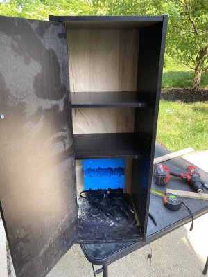
This was today’s progress. I removed the cardboard backing and cut plywood to replace it. Drilled some holes in the particle board and popped in some anchors for screws. I installed my amazon recessed power strip on the bottom. Cut the holes for the 4 gang outlet boxes. Cut the false panel to fit and cut the shelves back so that there will be 3” of space between the panel and the front door.

The top shelves will be where the raspberry, PCA 9685, motor drivers, and circuit board will be. The goal is to make it easy to pull out. Kind of like a blade in a switch for those IT guys out there. The middle shelf will be forcable management, and the bottom is going to have a PVC box housing the relays.

3B9F7D9A-9BBB-40CD-99A3-A3988EAF8424.jpeg
3E5955C0-5CBF-4512-A767-4E6A498FA22A.jpeg
FE186815-54E1-45DF-B891-F84CA5922A59.jpeg
A5C02E72-70B8-4965-9A02-C18ECC040CFD.jpeg
E4996AA4-88FF-46EE-AEAF-B3EF03BE964B.jpeg
EAE7F230-E8F4-49BE-BF30-52D220F96988.jpeg
26A63A7E-1186-4394-86A6-505B038D5D9E.jpeg
 
OP
OP
b4tn

b4tn

Valuable Member
View Badges
Joined
Jun 17, 2015
Messages
1,673
Reaction score
2,241
Location
Columbia MD
Rating - 0%
0   0   0
Not much to update. I did order a whole slew of parts though. Here is my shopping list.


I am having a heck of a time finding a box sized correctly to house the relays. I really did not want them to be mounted out in the open but its looking like I will be mounting them to a board or sheet of plexi maybe. after lots of mulling over ideas I have decided to do most of my interconnections with rj45 for the relays and the doser motors. PWM and DC switched ports are going to utilize 5.5x2.5 barrel connectors, and temp probes will be using USB 2.0 plugs.
 

Ranjib

7500 Club Member
View Badges
Joined
Apr 16, 2016
Messages
9,843
Reaction score
17,056
Location
Pleasant Hill, Concord
Rating - 0%
0   0   0
Not much to update. I did order a whole slew of parts though. Here is my shopping list.


I am having a heck of a time finding a box sized correctly to house the relays. I really did not want them to be mounted out in the open but its looking like I will be mounting them to a board or sheet of plexi maybe. after lots of mulling over ideas I have decided to do most of my interconnections with rj45 for the relays and the doser motors. PWM and DC switched ports are going to utilize 5.5x2.5 barrel connectors, and temp probes will be using USB 2.0 plugs.
this is a big pain i think. Housing for scratch build power controllers. Metal enclosures are most preferred but hardest to fabricate/customize. Wood is in between and most plastic made ones are fire hazard
 
OP
OP
b4tn

b4tn

Valuable Member
View Badges
Joined
Jun 17, 2015
Messages
1,673
Reaction score
2,241
Location
Columbia MD
Rating - 0%
0   0   0
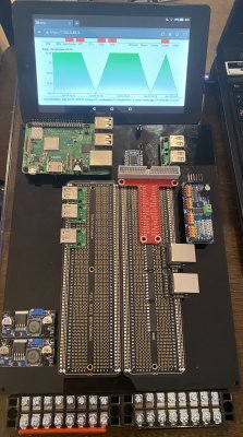
Spent a little time today on the main board. I got all the holes drilled and stand offs in place. It took some figuring on how I was going to interconnect and lay everything out but I finally figured out how I want everything to sit. I also picked up a used fire tablet that will be my new screen for inside the enclosure.
Still waiting on some parts but here is a quick shot of what’s going on now.

A55D7474-1F79-48CA-9FCD-6E9DA4D26AA0.jpeg
 
OP
OP
b4tn

b4tn

Valuable Member
View Badges
Joined
Jun 17, 2015
Messages
1,673
Reaction score
2,241
Location
Columbia MD
Rating - 0%
0   0   0
I officially have two reefpi’s! I’m missing one motor driver but hopefully it will be in next week. All the wires are ready for it so I should just be able to drop it in. I had planned on getting all the pins mapped and configured tonight so I could start testing But spent the better part of 3 hours trying to figure out why nothing worked. I was getting 0 volts after the ribbon cable on both the 5 and 3 volt pins. My circuit checked out so I was thinking the cable was bad. I continuity checked all 20 pins, pulled the boards looking for solder bridges, and was about 5 minutes from de-soldering chips when I figured I would double check the ribbon plug orientation. Glad I did! I had the plug in backwards which makes zero sense and looks backwards based on where the pins are located but it works now.

I still have a long ways to go. I need to tidy up the wiring, make a whole bunch of custom USB and Ethernet cables, build the relay board, wire the outlets, and finish drilling holes as well as paint the cabinetry.

These DROK temp probes are way over built. Super quality stuff. And I really like the USB fitting. It’s a lot more sturdy than my previous setup.

E0A7628E-E120-4C00-AAE0-93D502C633B0.jpeg
F10FD1E9-0500-4EC7-8268-91A6AF950827.jpeg
7D9369A2-BB29-4A4A-8C3D-00800E322719.jpeg
 
OP
OP
b4tn

b4tn

Valuable Member
View Badges
Joined
Jun 17, 2015
Messages
1,673
Reaction score
2,241
Location
Columbia MD
Rating - 0%
0   0   0
More progress. The additional TB6612 motor driver arrived today so I plopped it in. So far all circuits are finished and I am testing all the outputs and inputs. I have tested the ATO, temp probes, all 4 dosers, one outlet from each of the 2803’s and all the PCA9865 outlets that are configured as switches. So far all tests ok.

Typical me I have changed my design idea a bit. since I don’t really have a need for PWM outputs. And since I have lots of Mounting room for additional breakouts and loys of extra design space on the board I’m going to skip PWM outputs for now. But will have the ability in the future if needed. So instead I will have 16 controllable AC outlets and 8 DC controllable outlets. The ida for the DC outlets will be to have 8 external barrel jacks for standalone DC power switch by the relay. This is going to be for things like auto water changes or any other DC powered pumps.

Testing the dosers for power and speed with a small fan.

2A07F231-26A2-4E7D-A973-E43455539E18.jpeg
 
OP
OP
b4tn

b4tn

Valuable Member
View Badges
Joined
Jun 17, 2015
Messages
1,673
Reaction score
2,241
Location
Columbia MD
Rating - 0%
0   0   0
So my wife asked me if I’m going to work on the R2-D2 wire thingy tonight. So the second reefpi now has a name

R2-D2
Second generation Reefpi, Dev series two

:) lol
 
OP
OP
b4tn

b4tn

Valuable Member
View Badges
Joined
Jun 17, 2015
Messages
1,673
Reaction score
2,241
Location
Columbia MD
Rating - 0%
0   0   0
The main circuit is complete, tested, and configured in reefpi. I still need to build the relay board and wire the outlets. Once that is complete I need to start making custom USB, ethernet, power cables, and mount the plugs on the enclosure. Some things to note:

- All grounds are shared except for the Independent DC power supplies. On the back of the enclosure I will have 4 plugs for 4 separate relay controlled DC power blocks.

- I have an arctic 80mm fan for cooling inside the enclosure. It will be controlled by an internal temp probe. The fan is dead silent though so most likely I will just leave it on but hey coolness factor lol

- I had a bad experience with the pi 3v source and a single momentary short fried my whole raspberry. So for safety sake I have a separate buck converter for the 3 volts required to operate the autofeeder. The autofeeder is activated by a momentary 3v presence on its control wire. On my current setup this is done with a transistor but everytime the reefpi power cycles its activates the feeder so I am doing this one on a relay. Info on the autofeeder mod is here. https://www.reef2reef.com/threads/r...ler-based-on-raspberry-pi.289256/post-7268673

- One AC relay bank will be configure as Normally open and the other will be Normally closed. More info on that is here. https://www.reef2reef.com/threads/another-reef-pi-build.506894/post-5434598

And because I like diagrams.. This is whats built so far minus the relays.


R2D2.jpg
 
Last edited:
OP
OP
b4tn

b4tn

Valuable Member
View Badges
Joined
Jun 17, 2015
Messages
1,673
Reaction score
2,241
Location
Columbia MD
Rating - 0%
0   0   0
That was time consuming! And officially the last of my stand offs I had to Dremel a few shorter to fit. They are held to the board with small wood screws
D546094E-1F69-47D5-B6EE-36D849CCEA41.jpeg
6C3D795B-C187-4BA5-B976-C5F637BC4E21.jpeg
D956329E-F534-4692-8C45-0F67B0A60AF5.jpeg
 
OP
OP
b4tn

b4tn

Valuable Member
View Badges
Joined
Jun 17, 2015
Messages
1,673
Reaction score
2,241
Location
Columbia MD
Rating - 0%
0   0   0
I forgot how much I hate painting!! I pretty much gave up trying to get a smooth finish. But I’m at the point now where I need to get things painted and put together before I start doing internal wiring. The black pipe is just some PVC. It’s a pass through so that I can pass cables through the center and mount controllers to the front panel. Rather than flush mounting the screen I decided to make a shelf with a lip to hold it. This way I can easily pick it up, take it to the couch, or whatever. The inside is getting painted winter gray. The outside will be black.
CDA71FFA-044D-40F5-A206-57DAA7B304AC.jpeg
2B945645-B13C-49FC-9940-467DEF600137.jpeg
293C8960-5A95-4A17-BF18-684B41A7A84D.jpeg
10A95BD4-D418-4DA0-B057-1697F4DB01FF.jpeg
013F2643-C3EE-4845-8020-AD62C657F1C4.jpeg
 
OP
OP
b4tn

b4tn

Valuable Member
View Badges
Joined
Jun 17, 2015
Messages
1,673
Reaction score
2,241
Location
Columbia MD
Rating - 0%
0   0   0
It’s so humid here that it’s taking forever for paint to dry. I have so little patience when it comes to paint. It’s been 48 hours and it’s still tacky but I started test fitting and assembling anyway.
523C8478-5353-4E71-B62E-6E562E78742F.jpeg
EC48E2CA-6AFD-43BC-982C-C196E8DA69C0.jpeg
 
OP
OP
b4tn

b4tn

Valuable Member
View Badges
Joined
Jun 17, 2015
Messages
1,673
Reaction score
2,241
Location
Columbia MD
Rating - 0%
0   0   0
Well, summer brought about a big floating distraction! But this reefpi has been staring at me every night. As boat season starts ramping down I’m having more time at home for projects. I couldn’t decide where to start back up so I figure I would start with the outlets. My least favorite part.
BCB52C61-75A5-4E74-8237-ECA2B8E9D053.jpeg

53C9CAD3-B56C-4090-8332-1D7AA9CAA9DD.jpeg
 
OP
OP
b4tn

b4tn

Valuable Member
View Badges
Joined
Jun 17, 2015
Messages
1,673
Reaction score
2,241
Location
Columbia MD
Rating - 0%
0   0   0
I made a lot of progress today. I had to reference my original build thread and diagram I made for outlets but I got the relay board all wired up. Was very tedious and I’m glad I’m done.


8CCE672C-9087-4986-B424-171F7F3606FA.jpeg

I also did some math just to be certain. Total wattage on the wall outlet, assuming I have all lights, pumps, and heaters running at full blast (which they never are) is 1270 watts or 11.2 amps. Everything is on a 15 amp GFCI circuit. The 16 reefpi switching outlets will have an 840 watt load or 7.4 amps. All 16 of the reefpi outlets are also protected by a 10 amp fuse. It’s all getting close to the max but I feel pretty good about those numbers knowing that nothing runs 100% or all at the same time.

FA82CA53-B52F-4B38-B930-A4B74EBE9601.jpeg
60276819-E143-4888-AF90-72CF0E21BE6D.jpeg
95330DB0-BF49-4603-84CB-84FD1B02A52A.jpeg


Break time

29D6E5D3-E4D9-4AD7-85F3-6FBF482BCE28.jpeg
 

Being sticky and staying connected: Have you used any reef-safe glue?

  • I have used reef safe glue.

    Votes: 128 88.3%
  • I haven’t used reef safe glue, but plan to in the future.

    Votes: 8 5.5%
  • I have no interest in using reef safe glue.

    Votes: 6 4.1%
  • Other.

    Votes: 3 2.1%
Back
Top