DIY EC sensor

Sral

Valuable Member
View Badges
Joined
May 2, 2022
Messages
1,005
Reaction score
971
Location
Germany
Rating - 0%
0   0   0
Since Atlas Instruments EC sensors are expensive as hell, I looked around a bit and stumbled upon this DIY build.
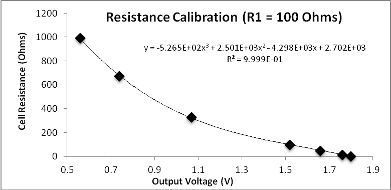
It basically measures the voltage across a voltage divider, with the resistor under test being a DIY probe:
conductivity_example.png

As far as I understand:
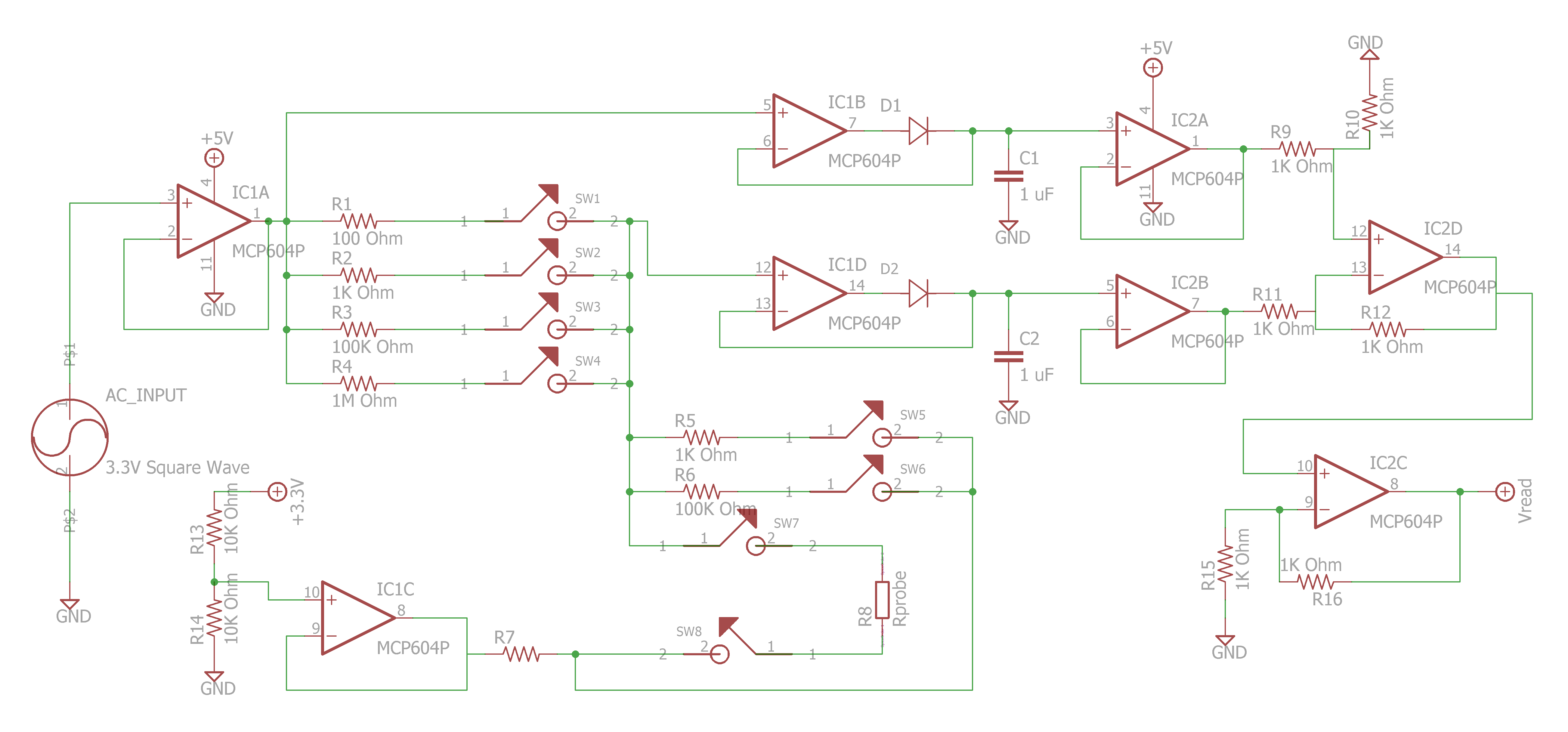
  • The circuit uses AC excitation (IC1A on the left)
  • to drive a voltage divider
    • R1,R2,R3,R4 as variable known resistors
    • best accuracy with the resistor that's closest to the probe under test
    • R5 and R6 as known reference for drift correction
    • R8 the probe under test
  • Measurement is done with:
    • two peak discriminator circuits that measure:
      • peak voltage of the excitation at IC1B
      • peak voltage of the voltage divider at IC1D
    • Both peak voltages are compared in IC2D and amplified at IC2C

Do you think that's usefull in a Reef-Pi vs open water ?
  • It will obviously need good isolation and a lot of testing (especially for safety)
  • I think it might benefit from bipolar AC excitation
  • Inspired from this approach:
    • he uses a power plug as probe, because why not :D
    • I'm thinking about using a TRRS gold plated audio connector. It's :
      • chemically resistant
      • hopefully watertight (needs testing)
      • has short standardized contact spacing
      • 4 contacts, the middle two can be used for measuring and the outer maybe for grounding to limit the effects in the water and proximity to other things around.
      • when you assume a 1mm contact spacing with values of 100-1000µS/cm you get around 10kOhm and 100kOhm which is just in the middle of the above setup.
 
Last edited:
OP
OP
S

Sral

Valuable Member
View Badges
Joined
May 2, 2022
Messages
1,005
Reaction score
971
Location
Germany
Rating - 0%
0   0   0
Just noticed: the excitation runs against a virtual ground at 2.5V, so it is actually bipolar at the probe.
I also found the switch he uses: MAX395CWG
Problem I see with this: the excitation might be 2.5V pk-pk AC around a virtual ground, but that means the tank will always be connected to virtual ground at 2.5V. Since we would be measuring very small currents (10µA - 50µA from 2.5V over 150kOhm - 60kOhm, FRESH WATER) we probably need good isolation very badly to not lift the tank to 2.5V and have currents everywhere.

That's probably also the reason for R7 (no idea what size that one is), it limits the current from virtual 2.5V ground to the water.
 
OP
OP
S

Sral

Valuable Member
View Badges
Joined
May 2, 2022
Messages
1,005
Reaction score
971
Location
Germany
Rating - 0%
0   0   0
Got an idea: one could couple the resistor circuit using a RC high-pass filter. Resitance needs to be much lower than the resistance cascade, so 1/100 of something like 60 kilo Ohm:
R=600 Ohm C=1µF => f_crit=1667 Hz
V_max = 5 Volt => I_max = 8mA
Salt water would need lower resistance overall and therefore a bigger capacitor for the same frequency cutoff.

That way the resistor circuit actually oscillates around 0 V, which might leed to less interference. A Bigger Cap makes it better.
Problem is however that the OP-Amp would have to sink current, which it isn't designed for I guess.
 

robsworld78

Well-Known Member
View Badges
Joined
Feb 14, 2020
Messages
952
Reaction score
1,280
Location
Edmonton, Canada
Rating - 0%
0   0   0
I love what you're trying to do here, I wish I could be more help but most of this is over my head. I have seen those friendly 1 resistor circuits :beaming-face-with-smiling-eyes: which is something I can understand but yeah based on videos it's not accurate enough, at least for not my purpose.

Here's another DIY version, someone made a video showing how it works on a oscilloscope which is nice.


This is the source, it looks similar to what you posted.


You'll see the probe he's using, might be easier than making one. You could strap a temp sensor to it.

I'm definitely following along and I'm going to try and work on something as well, if I come up with anything or info you might need I'll certainly let you know.
 
OP
OP
S

Sral

Valuable Member
View Badges
Joined
May 2, 2022
Messages
1,005
Reaction score
971
Location
Germany
Rating - 0%
0   0   0
Nice. Interesting thing however: we now see 3 different methods of measuring ^^
  • my Link:
    • measures peak voltage over a voltage divider
  • your video:
    • the first Probe measures using the discharge of a capacitor over the probe
    • the DIY build uses the probe to change the amplification of an OP-Amp
      • (which is somewhat similar to my Link, but not quite)
I'll probably try to build the one from my link, because I think it may have less drift. With the OP-Amp one you constantly need to correct the OP-Amp and system offsets to get an accurate reading, because those offsets get amplified. Whereas the circuit from my link mostly uses unitary Gain Signal followers and barely any amplification. It therefore passes more current through the water, but should be more error and drift tolerant.
 
OP
OP
S

Sral

Valuable Member
View Badges
Joined
May 2, 2022
Messages
1,005
Reaction score
971
Location
Germany
Rating - 0%
0   0   0
Alright, I did some calculations, what the planned circuit should give as an output voltage for a given resistance from the EC probe in the water:
image.jpg


It basically follows these curves for the test resistor value vs output voltage for different known resistors R1 (mind the log scale). So using different reference resistors allows a good range.
TestResistorVsVoltage_log.png

Here a linear plot for R1 = 100 Ohm:
TestResistorVsVoltage_comparison.png

Which agrees well enough with the experimental values from the original publication:
image007.png

I believe the differences are due to non-ideal behavior of the used operational amplifiers, e.g. input offsets and currents. I might have to switch them out for compensated ones.

I also calculated the capacitance needed to AC couple the driving AC current. This is to prevent the probe from lifting the tank to 1.65 V that the virtual ground is set to. We don't want our measurement to interfere with pH measurement after all ^^

Using 1kHz driving frequency, 1k ohm combined resistance and a maximum of 1% signal drop gives a reasonable 1,1 micro farad as minimum value. I think that is manageable ^^
image.jpg


Next up: test circuits on a pluckable board !

I also went with @robsworld78‘s advice and bought a cheap EC probe with a BNC connector from Amazon to compare to the nickel plated audio jack.
 
Last edited:
OP
OP
S

Sral

Valuable Member
View Badges
Joined
May 2, 2022
Messages
1,005
Reaction score
971
Location
Germany
Rating - 0%
0   0   0
Alright, I built the first test circuit, as described in the first post.
Slight changes here:
  • variable frequency signal generator on the left
    • cheap one off of amazon, not realy good choice, but it's at least easily sweepable
    • I used a Sine waveform for now
    • signal stepped down with 2 resistors (top left corner) and fed into the circuit
  • instead of using two resistors from 3,3V to GND I used a simple RC-circuit to smooth the input to its DC average
    • bottom left corner, the 10µF capacitor the black probe is connected to
    • fed by a 15k Ohm resistor
  • the manual for the OP-Amps recommends to not feed large capacitive loads without a current limiting resistor in order to reduce ringing. For my frequency range the manual states something like 10-20 Ohm, so I added those to the original design
    • right side, feeding the 2 "identical" 1µF capacitors that store the peak voltage signal descriminated by the also "identical" signal diodes on the right side of the OP-Amp IC
TestCircuit.JPG

This gives nice enough behavior for now, when I measure it with a simple multimeter. For simplicity, AC signals are on the left, DC signals are on the right:

Measurement​
VDC​
VAC​
Measurement​
VDC​
VAC​
Signal Generator~3.492V~1.818VRC average~1.055V~0.001V
Stepped Down~1.057V~0.517VVirtual GND~1.057V~0.001V
Excitation (VTOT)~1.056V~0.517VTotal Peak~1.606V~0.000V
Test (VTEST)~1.057V~0.256VTest Peak~1.331V~0.000V
 
Last edited:
OP
OP
S

Sral

Valuable Member
View Badges
Joined
May 2, 2022
Messages
1,005
Reaction score
971
Location
Germany
Rating - 0%
0   0   0
Nice behavior, since the OP-Amp inputs have a maximum input offset of 2mV. Here are the waveforms as measured with my cheap oscilloscope off of Amazon:
VTOT, same as Stepped down Signal, as shown above:
Vtot.jpg

Then the Test voltage, meaning the votlage on the resistor under test (in this case 2 "identical" 1.4k 1% resistors:
Vtest.jpg

With the virtual Ground firmly set in the middle:
VGND.jpg

The Peak detectors are similarly featureles.

I looked at the total Peak voltage in the range of ~100 Hz to ~65 kHz and it stayed stable at ~1.606V DC until about ~30kHz when it started dropping to about ~1.550VDC towards the ~65 kHz. Sadly my multimeter can't measure AC voltages above a few kHz anymore, so I am having a hard time checking where the problem occurs. For know I now that the circuit works in the desired range of a few kHz and I can proceed ! :D
 
OP
OP
S

Sral

Valuable Member
View Badges
Joined
May 2, 2022
Messages
1,005
Reaction score
971
Location
Germany
Rating - 0%
0   0   0
Plans for the final excitaton circuit:
  • I'll test if I can use AC coupled excitation as well
    • one thing to watch out here: this will cause NEGATIVE VOLTAGES on the OP-Amp inputs. which it doesn't like, since the inputs are diode protected to GND.
    • Those will start conducting from GND to those negative voltages and probably break the diodes and the OP-Amps in the process
    • In order to not break those I will have to add ~3k current limiting resistors on the VTOT and VTEST inputs
  • Doing so will free up the VGND generating OP-Amp input which I will use to build a simple square wave resonator, amplified by a mosfet
    • problem here: I will need a stable voltage source on the oscillator to get accurate results
    • my 5V supply on the I2C comes from a step-down converter, so it is quite ripply and jumps around a bit regularly
      • periodic changes from ~5,08V to 5,04V
    • I will therefore build an input voltage circuit with ripple reduction using a capacitance multiplier and one of the 3,3V regulators that @robsworld78 sent me, good thing he included those ^^
 

Ranjib

7500 Club Member
View Badges
Joined
Apr 16, 2016
Messages
9,825
Reaction score
17,041
Location
Pleasant Hill, Concord
Rating - 0%
0   0   0
Alright, I built the first test circuit, as described in the first post.
Slight changes here:
  • variable frequency signal generator on the left
    • cheap one off of amazon, not realy good choice, but it's at least easily sweepable
    • I used a Sine waveform for now
    • signal stepped down with 2 resistors (top left corner) and fed into the circuit
  • instead of using two resistors from 3,3V to GND I used a simple RC-circuit to smooth the input to its DC average
    • bottom left corner, the 10µF capacitor the black probe is connected to
    • fed by a 15k Ohm resistor
  • the manual for the OP-Amps recommends to not feed large capacitive loads without a current limiting resistor in order to reduce ringing. For my frequency range the manual states something like 10-20 Ohm, so I added those to the original design
    • right side, feeding the 2 "identical" 1µF capacitors that store the peak voltage signal descriminated by the also "identical" signal diodes on the right side of the OP-Amp IC
TestCircuit.JPG

This gives nice enough behavior for now, when I measure it with a simple multimeter. For simplicity, AC signals are on the left, DC signals are on the right:

Measurement​
VDC​
VAC​
Measurement​
VDC​
VAC​
Signal Generator~3.492V~1.818VRC average~1.055V~0.001V
Stepped Down~1.057V~0.517VVirtual GND~1.057V~0.001V
Excitation (VTOT)~1.056V~0.517VTotal Peak~1.606V~0.000V
Test (VTEST)~1.057V~0.256VTest Peak~1.331V~0.000V
This is looking very cool :)
 
OP
OP
S

Sral

Valuable Member
View Badges
Joined
May 2, 2022
Messages
1,005
Reaction score
971
Location
Germany
Rating - 0%
0   0   0
Okay, I read up on the oscillator circuit and that got me thinking. They mentioned that the slew rate of the OP-Amp is important for the rectangle waveform. I think that this might be the reason why my peak detector doesn’t work well anymore at above 30kHz. My peak detector OP-Amp itself might not be able to ramp up fast enough to the peak value in the shorter and shorter amount of time, that the input actually rises above the peak voltage stored in the capacitors at higher and higher frequencies. In the site about OP-Amp oscillators I looked at, they used a LF411 for higher frequencies, which has a slew rate of ~13volt/microsecond, vs my MCP604, which has 2.3 Volt/microsecond or so.

so for higher frequencies it might be a good idea to use an OP-AMP that’s much quicker than the main excitation frequency.
 
OP
OP
S

Sral

Valuable Member
View Badges
Joined
May 2, 2022
Messages
1,005
Reaction score
971
Location
Germany
Rating - 0%
0   0   0
Okay, I retract everything I have said. I looked at the signal from my oscillator and it's amplitude decreases slightly towards higher frequencies, so it's actually the oscillator. The Circuit might be absolutely fine.
 
OP
OP
S

Sral

Valuable Member
View Badges
Joined
May 2, 2022
Messages
1,005
Reaction score
971
Location
Germany
Rating - 0%
0   0   0
I reworked the circuit for AC-coupled excitation:
  • I put a 10µF capacitor in series in between the excitation voltage and the two resistors
  • connected the end of the two series resistors to actual Ground instead of the virtual ground (one output of my OP-Amp @ constant voltage in between the AC swings)
  • included 3,3 k resistors as current limiters to my OP-Amp Inputs for the peak detector to protect them from negative voltages
Works nicely, gives symmetric voltage swing around something like 0:
VAC_Coupling.jpg

Same Measurements with a multimeter:
MeasurementDCACMeasurementDCAC
Excitation (VTOT)~0.025V~0.483VVTEST at input~0.012V~0.238V
VTEST~0.012V~0.235VV_PEAK_TOT~0.607V~0.000V
VTOT at input~0.054V~0.450VV_PEAK_TEST~0.303V~0.000V

So absolutely lucky perfect values ^^
I am currently using two "identical" 1.4k 1% resistors, so i would expect V_PEAK_TEST to be around half of V_PEAK_TOT, but to be THAT close surprises me :D

I'll have to see whether I can get rid of the remaining DC component, maybe by using another coupling capacitor that has lower leakage current or different capacity. However, maybe it is not even a concern, we'll see ^^
 
OP
OP
S

Sral

Valuable Member
View Badges
Joined
May 2, 2022
Messages
1,005
Reaction score
971
Location
Germany
Rating - 0%
0   0   0
Work progresses, I built the oscillator for about 3 kHz:
V_Oscillator.JPG

Scale is noted at the bottom. Output is rail-to-tail from the OP-Amp (simplest possible oscillator), as you can see the period is about 280µs, so about 3,5 kHz. Nailed it !

Since I need a nice reference voltage, I looked at my VCC ripple:
VCC_Ripple.JPG

Scale is noted at the bottom. You see 50mV spikes at the switching frequency of something like 25µs or 40kHz. I used a capacitance multiplier to smooth this out:
VCC_Reduced.JPG

Scale is the same, looks nice ! Problem however from what I have seen before: the voltage also has slower periodic spikes every 2.5s or so:
V_Reduced_artifacts.JPG

I'm afraid this might be my SCD30 CO2 meter measuring every 2s, which draws an AVERAGE of 19mA, but I guess this is concentrated in about the few 100ms that you see there ... so there it becomes ~160mA (2.5s/0.3s*19mA) which seems to tax the supply voltage on my I2C connections. Maybe I need to add a capacitor to the air Quality module to reduce this. Problem of course: I don't think there is a useful capacitor than can do this. If you would want to supply 160mA over 0.3s with a drop of just 10mV you would need a capacitor of 4.8 farad :grinning-face-with-sweat:
(4.8 F = 160mA*0.3s / 0.01 V)
This is of course ignoring the simultaneous power input through the VCC line, but it shows the magnitude your at in this situation, since even a few 100mF are still quite the punch !

However, I think I can proceed with the 3.3V regulator and MOSFET. Onwards !
 

Ranjib

7500 Club Member
View Badges
Joined
Apr 16, 2016
Messages
9,825
Reaction score
17,041
Location
Pleasant Hill, Concord
Rating - 0%
0   0   0
There is no way to isolate or reduce the impact of co2 meter induced spikes like something equivalent to galvanic isolation? Or do we need something on the software side to filter it out ?
great progress by the way and thank you for taking the time to write down and sharing your learning with us. I find it fascinating and joyful
 
OP
OP
S

Sral

Valuable Member
View Badges
Joined
May 2, 2022
Messages
1,005
Reaction score
971
Location
Germany
Rating - 0%
0   0   0
Well, the only way I could think of is to improve the power connection between my DC/DC converters to the SCD30. Currently that's done by the use of (quite a few) header pin and cable connections. Maybe that has too much contact resistance or too much cable resistance. The other way would be to add a capacitor to the SCD30 power to hopefully smooth that out a bit.
Just calculated: 10mV drop from 160mA is just 62m Ohm ... not that much actually.

It's only a 10mV drop and spike after all, which is smaller than the +/-25mV ripple on the line. I'll try a capacitor right next to the SCD30 and get back to you.

Yesterday I finished the test setup and the result is good enough for starters. There are some problems that I'll have to solve, but for now I'm happy. The output signal I got for a reference resistor of ~1.4k 1% with two test resistors:
~1.4k Ohm 1% VOUT=(1.875+/-0.004) V
~887 Ohm 1% VOUT=(2.238+/-0.004) V
inf Ohm VOUT=(0.106+/-0.001) V

So even with the 10mV drops and spikes the output signal is stable to about 4mV right now, which might be good enough.

Two problems right now:
- peak voltage storage capacitor is 1µF and discharged only by the input current on the OP-Amp pins, which takes FOREVER to discharge after you disconnected the test resistor, maybe I'll have to decrease capacitance, or include a large discharge resistor
- I get signal distortion from the OP-Amp inputs on my AC excitation
----> happens especially at large resistances (like infinity for example)
----> the protection diode on the input basically discharges my AC coupling capacitor through the input resistor
----> I'll have to either AC couple signal input and/or use a much larger input resistor

Nothing unsolvable though ^^
 
OP
OP
S

Sral

Valuable Member
View Badges
Joined
May 2, 2022
Messages
1,005
Reaction score
971
Location
Germany
Rating - 0%
0   0   0
Alright, I solved the reaction time issue by discharging the capacitor that stores the peak voltage with a 10 M Ohm resistor to ground. Works like a charm :D

The other problem, where negative signals are clamped by the OP-Amps input protection diode is a bit more tricky. It basically arises from using a SINGLE RAIL Op Amp together with AC EXCITATION, so negative input voltages. Either using a double rail OP-Amp OR a virtual 1.65V Ground would make it easier. Sadly, I don't have dual power rails or an IC that can generate one, nor a dual rail OP-Amp. When you use a 1.65V Virtual ground you would need good isolation, since it would otherwise raise the tank to 1.65V, which I would like to avoid ^^

I had a few ideas:
- use a larger signal input resistor
----> if it's too large the signal at the OP-Amp actually gets too low (100k drops the peak from 1.65V to about 1V)
----> when the conductivity gets very low the measurement resistors also become very large, so one would need an even larger input resistor to get the same effect
----> impractical by itself
- use a diode to protect the input from negative voltages
----> also cuts the signal by ~0.8V, so I would not be able to measure voltages below 0.8V ... which is actually where I want to measure, since everything far above 1V would start to create hydrogen (as far as I am informed)
- AC couple the input signal
----> the protection diode would still charge the capacitor reversely, lifting the input signal until it doesn't drop below the diode's voltage of -0.8V
----> this heavily changes the detected peak voltage, so not useful

I am currently thinking about combining a parallel load resistor on the excitation to keep the AC coupling capacitor charge constant, irrespective of the test and reference resistor, together with a signal input resistor that's just large enough. By doing the first I can hopefully use a much lower signal input resistor. Fingers crossed ^^
 
OP
OP
S

Sral

Valuable Member
View Badges
Joined
May 2, 2022
Messages
1,005
Reaction score
971
Location
Germany
Rating - 0%
0   0   0
Ha, works !

Just provided some base load on the AC coupling resistor and slightly increased the input resistors to 15k Ohm. Now the peaks read about 1.592+/-6mV VTOTAL and 0.792+/-4mV VTEST, with a total output signal of 1.592+/-6mV VOUT. Perfect !

Now I need to check which resistances I typically have to measure and test switching between several reference resistors with a digital switch IC.

@Ranjib Any idea what conductivity range and probe is typical for reef tanks ?
 

A worm with high fashion and practical utility: Have you ever kept feather dusters in your reef aquarium?

  • I currently have feather dusters in my tank.

    Votes: 65 37.1%
  • Not currently, but I have had feather dusters in my tank in the past.

    Votes: 59 33.7%
  • I have not had feather dusters, but I hope to in the future.

    Votes: 25 14.3%
  • I have no plans to have feather dusters in my tank.

    Votes: 26 14.9%
  • Other.

    Votes: 0 0.0%
Back
Top