Gyres, forward and reverse

Users Who Are Viewing This Thread (Total: 1, Members: 0, Guests: 1)

BCSreef

Well-Known Member
View Badges
Joined
Jan 22, 2016
Messages
599
Reaction score
482
Location
Maineville, OH
Rating - 0%
0   0   0
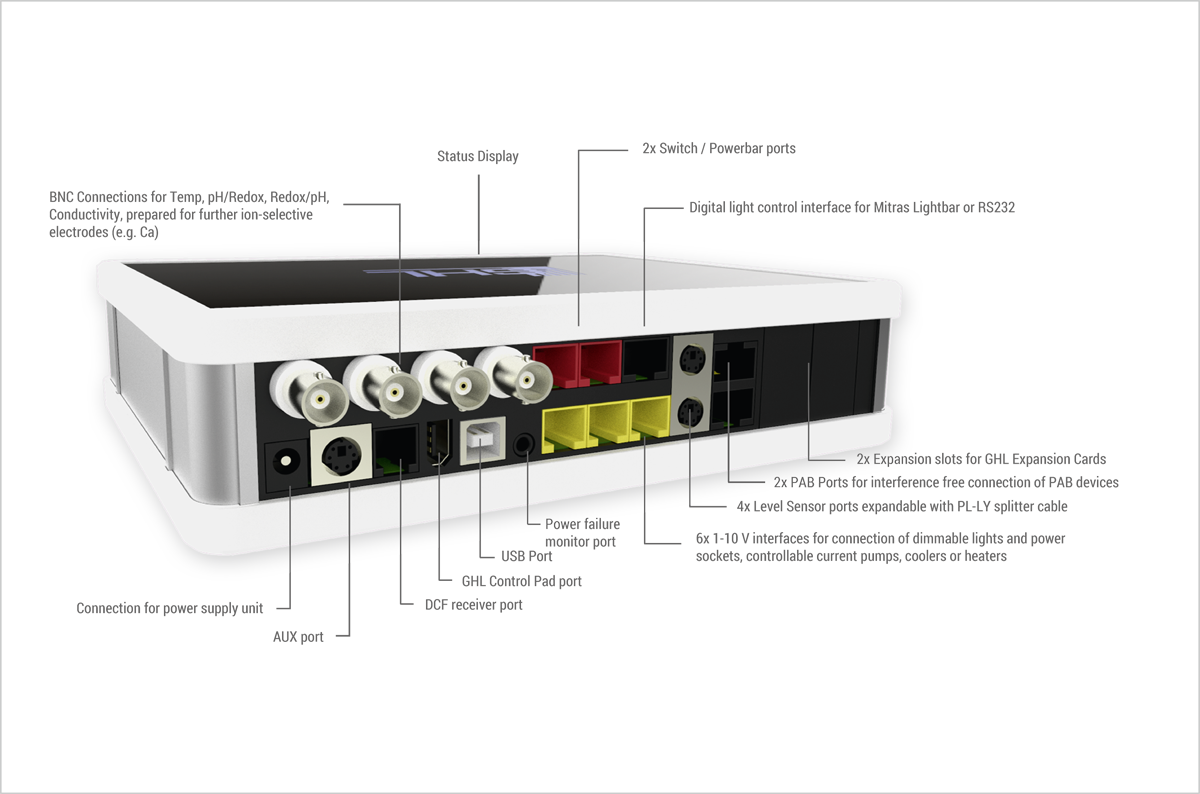
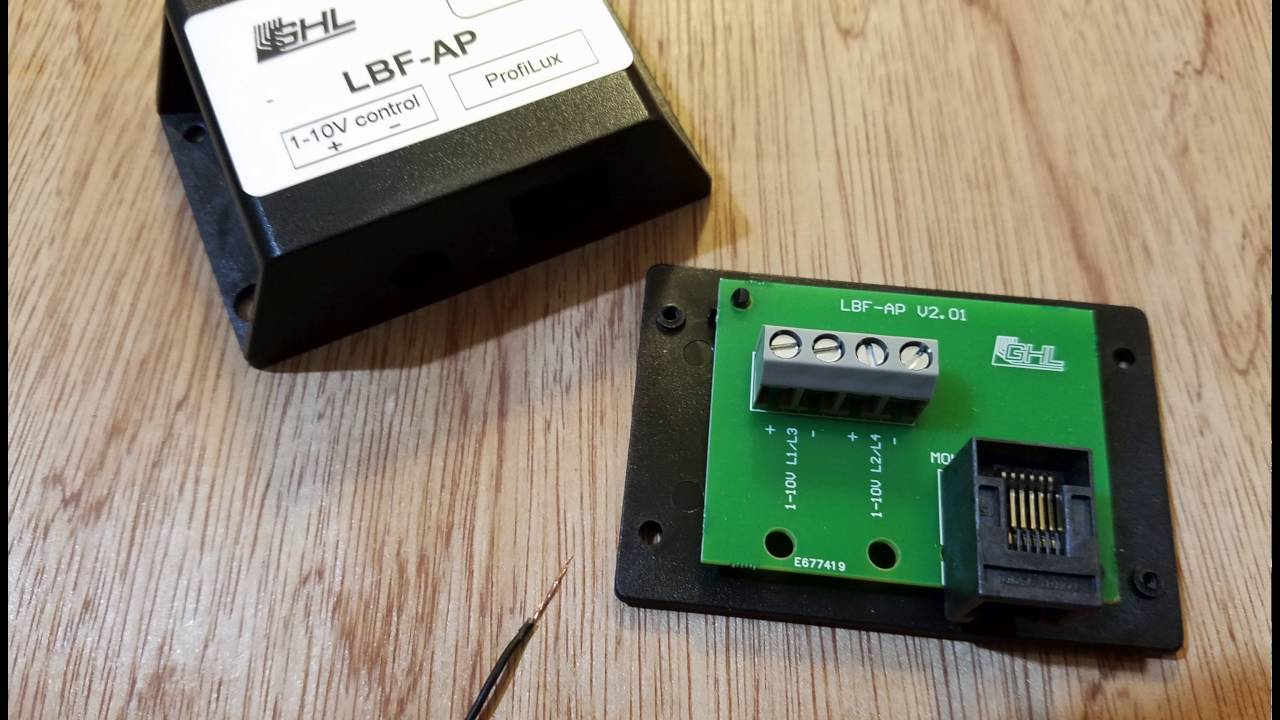
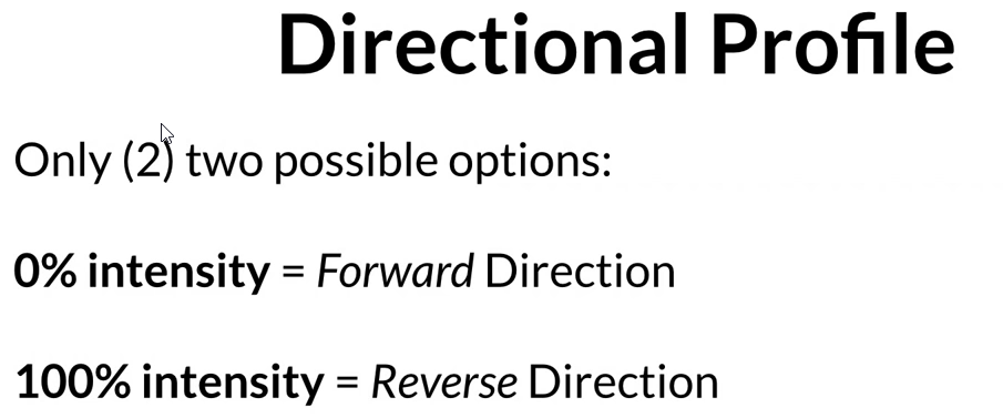
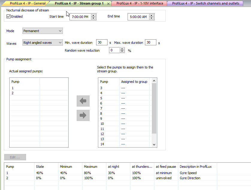
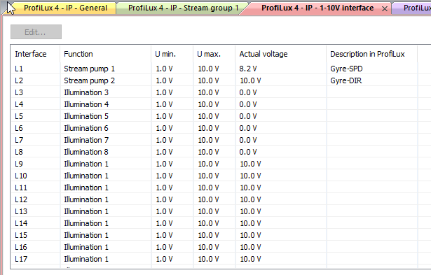
I am thinking about using the Ice Cap Gyre interfaces with a P4 to control 2 Gyre 150s. I understand the hardware needed and also understand how to wire and program the Gyres in the forward direction.. I know the Gyres can run in forward and reverse with Apex. Is anyone able to run their Gyres in reverse using the P4 in conjunction with the Ice Cap hardware?

Thanks and Happy New Year!
 

Mark Gray

2500 Club Member
View Badges
Joined
Jul 13, 2015
Messages
2,957
Reaction score
2,827
Location
Athens GA
Rating - 0%
0   0   0
Following I have them but have not taken them out of the box they are for my new build, I have also seen some posts about 1 gyre not running fast enough when hooked to the Apex using 2 gyre's. did you buy the cable the one that comes with it will work but the other cable lets you do more
 

Support@GHLUSA

Team GHL
View Badges
Joined
Jul 27, 2016
Messages
614
Reaction score
418
Rating - 0%
0   0   0
Forward and reverse functions were 2 separate input channels, and required a different cable than the one that came standard with it, as such you would use 2 different 0-10v ports, and just it in program to use 2 different ports in same stream group.
 

Tristren

Well-Known Member
View Badges
Joined
May 16, 2017
Messages
786
Reaction score
808
Location
Ottawa
Rating - 0%
0   0   0
Forward and reverse functions were 2 separate input channels, and required a different cable than the one that came standard with it, as such you would use 2 different 0-10v ports, and just it in program to use 2 different ports in same stream group.

Hi Marco,

I'm very interested in this as well. Can you expand on how this would work please?

Meaning what cable, how to wire it through the GHL module, and the basic software settings?

Thanks in advance, Tony
 

Mark Gray

2500 Club Member
View Badges
Joined
Jul 13, 2015
Messages
2,957
Reaction score
2,827
Location
Athens GA
Rating - 0%
0   0   0
OP
OP
B

BCSreef

Well-Known Member
View Badges
Joined
Jan 22, 2016
Messages
599
Reaction score
482
Location
Maineville, OH
Rating - 0%
0   0   0
Forward and reverse functions were 2 separate input channels, and required a different cable than the one that came standard with it, as such you would use 2 different 0-10v ports, and just it in program to use 2 different ports in same stream group.

Hi Marco,

Thanks for the very rapid holiday reply! For each Gyre, a single GHL Breakout Box should support 2 1-10v channels. one for forward and 1 for reverse. Is that correct?

Thanks Again! Bob
 

Support@GHLUSA

Team GHL
View Badges
Joined
Jul 27, 2016
Messages
614
Reaction score
418
Rating - 0%
0   0   0

Tristren

Well-Known Member
View Badges
Joined
May 16, 2017
Messages
786
Reaction score
808
Location
Ottawa
Rating - 0%
0   0   0
Correct, you’ll need dual 0-10v channels, a single breakout box provides screw terminals for 2 channels. L1/2 or L3/4 etc
You would then go I to a stream group, assign both channels and, mode Opposite.

Have a look at my howto here:
https://www.reef2reef.com/threads/howto-0-10v-control-return-pump.274565/#post-3309377

Happy New Years everyone!

Thanks very much Marco. Forgive me if the is a basic question, but is the L1/L2, L3/L4 2 channels or 4?

My understanding (maybe from a video on setting them up for the apex?) is that for the gyre one channel controls the speed of the pump, and the other just switches forward and reverse.

So to control a pair or gyres in alternating mode that would be 4 channels (1 each for power, 1 each to switch f/r). Does that mean one or two LBF-AP modules?

Thanks again, and Happy New Year to you as well!

Tony
 

Support@GHLUSA

Team GHL
View Badges
Joined
Jul 27, 2016
Messages
614
Reaction score
418
Rating - 0%
0   0   0
@Tristren -
The 0-10v ports (Lx) are a physical RJ12 configuration, with dial channels per port.

Port 1 - L1 & L2
Port 2 - L3 & L4
Port 3 - L5 & L6

ProfiLux-4_Connections_1200x794.png


The "breakout box" - LBF-AP; has a single RJ12 cable between the Breakout box back to a single L port, breaking out L1/2 (or L3/4 or L5/6) to screw terminals.

maxresdefault.jpg


-----


I'm looking into the directional control - i'll post back shortly.
 

Support@GHLUSA

Team GHL
View Badges
Joined
Jul 27, 2016
Messages
614
Reaction score
418
Rating - 0%
0   0   0
@Tristren -
You are correct and I was mistaken regarding the directional control.
Rather than using the second channel for reverse speed control, it is used as a directional flip switch; Forward or Reverse. (I'll update my original howto. I didn't have the directional cable to test with at the time..)

-----------------

Still very simple implementation;

CoralVue states the following in one of their videos:
01.01.2018-10.16.png


Simple to implement..

I would like the following behavior:
Forward intensity = 40%
Reverse Intensity = 80%
Forward Time = 30 secs
Reverse Time = 30 secs

Participate on Feed Cycle; at Minimum intensity of 30%


  1. Assign next available Pumps to a single stream group. In my example I'm using Stream Group 1, and Pump 1 & 2
    • Pump 1 = Gyre Speed
    • Pump 2 = Gyre Direction (0 = Forward, 100 = Reverse)
  2. Set Pump 1: Minimum: 40, Maximum: 80, Night: 30, Behavior during Feed Pause: Minimum (check 1,2,3,4)
  3. Set Pump 2: (This is Direction switch!!) Minimum: 0, Maximum: 100, Night: 0, Behavior during Feed Pause: uninvolved
  4. SAVE
  5. Go to System -> 1-10v interface
  6. Select the L channels(in my example L1(spd) and L2(dir) - assign the proper Stream Pump channels (Pump 1 for L1, Pump 2 for L2)


01.01.2018-10.40.png


01.01.2018-10.41.png
 

Tristren

Well-Known Member
View Badges
Joined
May 16, 2017
Messages
786
Reaction score
808
Location
Ottawa
Rating - 0%
0   0   0
@Tristren -
The 0-10v ports (Lx) are a physical RJ12 configuration, with dial channels per port.

Port 1 - L1 & L2
Port 2 - L3 & L4
Port 3 - L5 & L6

ProfiLux-4_Connections_1200x794.png


The "breakout box" - LBF-AP; has a single RJ12 cable between the Breakout box back to a single L port, breaking out L1/2 (or L3/4 or L5/6) to screw terminals.

maxresdefault.jpg


-----


I'm looking into the directional control - i'll post back shortly.

Ok, great, thanks very much. So the LBF-AP is really an adapter for a bare wire to an RJ12. And it is also a splitter so you could connect two devices into one plug, provided you wanted them to behave exactly the same...

And so, because of the way the Gyre pumps work needing two channels to be fully functional, I'll need two LBF-AP units, each plugged into one jack on the profilux (or an expansion box).

Though if someone (with a really wide tank for example) wanted a pair of Gyres in sync at one end, they could use one LBF-AP. And if someone wanted to run two unidirectional pumps they could also do it through one ear LBF-AP.

Shame we can't skip the pair of IceCap controllers I'll also need to get, and just have the ProfiLux control the Gyres directly.


Thanks again, Tony
 

Tristren

Well-Known Member
View Badges
Joined
May 16, 2017
Messages
786
Reaction score
808
Location
Ottawa
Rating - 0%
0   0   0
@Tristren -
You are correct and I was mistaken regarding the directional control.
Rather than using the second channel for reverse speed control, it is used as a directional flip switch; Forward or Reverse. (I'll update my original howto. I didn't have the directional cable to test with at the time..)

-----------------

Still very simple implementation;

CoralVue states the following in one of their videos:
01.01.2018-10.16.png


Simple to implement..

I would like the following behavior:
Forward intensity = 40%
Reverse Intensity = 80%
Forward Time = 30 secs
Reverse Time = 30 secs

Participate on Feed Cycle; at Minimum intensity of 30%


  1. Assign next available Pumps to a single stream group. In my example I'm using Stream Group 1, and Pump 1 & 2
    • Pump 1 = Gyre Speed
    • Pump 2 = Gyre Direction (0 = Forward, 100 = Reverse)
  2. Set Pump 1: Minimum: 40, Maximum: 80, Night: 30, Behavior during Feed Pause: Minimum (check 1,2,3,4)
  3. Set Pump 2: (This is Direction switch!!) Minimum: 0, Maximum: 100, Night: 0, Behavior during Feed Pause: uninvolved
  4. SAVE
  5. Go to System -> 1-10v interface
  6. Select the L channels(in my example L1(spd) and L2(dir) - assign the proper Stream Pump channels (Pump 1 for L1, Pump 2 for L2)


01.01.2018-10.40.png


01.01.2018-10.41.png
That's really helpful, thanks very much.

And am I right in thinking that if you set Stream Pump 2 above (the direction channel) to run with a wave pattern it would switch direction accordingly.

Though as I write this I guess that you would be better off having L2 tied to a cyclical timer, switching off and on every 30 seconds or what have you?


I want to thank you again for being so helpful. I am sure that this would be much simpler if I actually had a ProfiLux.

Actually, I should say that I'm sure that this will be much simpler when I get my ProfiLux! And your excellent support before I even buy has certainly helped to cement my decision.


Cheers, Tony
 

Support@GHLUSA

Team GHL
View Badges
Joined
Jul 27, 2016
Messages
614
Reaction score
418
Rating - 0%
0   0   0
In my example above I cycle forward to reverse every 30 seconds, with a different reverse internsity vs the forward intensity.

Forward intensity = 40%
Reverse Intensity = 80%
Forward Time = 30 secs
Reverse Time = 30 secs
 
OP
OP
B

BCSreef

Well-Known Member
View Badges
Joined
Jan 22, 2016
Messages
599
Reaction score
482
Location
Maineville, OH
Rating - 0%
0   0   0
Thanks again Marco,

I ordered all the hardware and hopefully will have it all up and running in a mfew days. I'll post my results here when done.

In the meantime, I decided to try a "simulation" while waiting for the IceCap hardware. Based on Marco's examples, I set up the stream pumps and 1-10v to run my 2 Gyres (opposite sides of a 180) to run in anti-sync mode.

In order to have the speed voltages ramp up/down and the direction voltages to go from 0 to 10 without a ramp, I had to place the speed and direction "pumps" in separate stream groups. I also noticed that for "permanent opposite" mode to work, pump numbers had to be sequential.

I assigned Pump 1 (left Gyre speed) and pump 2 (right Gyre speed) to Stream Group 1. See screenshot.
upload_2018-1-2_16-50-49.png


I assigned Pump 3 (left Gyre direction) and pump 4 (right Gyre speed) to Stream Group 2. see screenshot.
upload_2018-1-2_16-53-46.png


I watched the simulated Gyre speeds and directions and it all seems to work like a charm.

However, I do have a concern. Can the Gyres handle a sudden direction reversal while running at high speed? I know that that is not best practice with most DC motors. Is there a way to sync direction reversal when Gyre speed is at or near zero? I don't see an obvious way to do it. Maybe the IceCap interfaces have a "soft" reversal. I guess I'll find out when I get the IceCaps wired up.

Thanks, Bob

upload_2018-1-2_16-50-2.png
 
OP
OP
B

BCSreef

Well-Known Member
View Badges
Joined
Jan 22, 2016
Messages
599
Reaction score
482
Location
Maineville, OH
Rating - 0%
0   0   0
Sorry, I had the wrong descriptions for the the individual pumps above. Below is the screenshot with correct pump descriptions. Sorry for the confusion.

upload_2018-1-3_11-45-21.png


Last edited:
OP
OP
B

BCSreef

Well-Known Member
View Badges
Joined
Jan 22, 2016
Messages
599
Reaction score
482
Location
Maineville, OH
Rating - 0%
0   0   0
I think I have everything working!

First, the wiring. When you cut off the apex connector and strip the outside sheath, you should see 4 different colored wires. The wires and their mapping to the 3.5 mm audio plug are as follows:

  • Solid green and solid orange are (-) polarity, the commons and both map to the base segment of the plug.
  • The orange wire with the white strip is (+) polarity, controls direction (0 V = forward and 10 V = reverse) and maps to the center segment of the plug.
  • The solid blue wire is (+) polarity, controls speed and maps to the tip segment of the plug.
I then connected the wires as shown in the photo below. Note that it does not matter which (-) terminal the solid green and solid orange connect to since they are the same circuit.

clip_image001.jpg


The way I have it wired 1-10V L1 controls the direction and L2 controls the speed of the Gyre.

Next post will deal with setting up GCC.

Breakout box.jpg


Breakout box.jpg
 
OP
OP
B

BCSreef

Well-Known Member
View Badges
Joined
Jan 22, 2016
Messages
599
Reaction score
482
Location
Maineville, OH
Rating - 0%
0   0   0
Sorry about the duplicate photos.

Also, I just noticed the blue wire has a white stripe. so white stripe = (+).

I set up the 1-10V as follows:
upload_2018-1-11_17-54-45.png


Note that Stream pumps 1 & 2 = the speed of the two different Gyres while stream pumps 3 & 4 control direction of the two different Gyres
 

Tristren

Well-Known Member
View Badges
Joined
May 16, 2017
Messages
786
Reaction score
808
Location
Ottawa
Rating - 0%
0   0   0
I think I have everything working!

First, the wiring. When you cut off the apex connector and strip the outside sheath, you should see 4 different colored wires. The wires and their mapping to the 3.5 mm audio plug are as follows:

  • Solid green and solid orange are (-) polarity, the commons and both map to the base segment of the plug.
  • The orange wire with the white strip is (+) polarity, controls direction (0 V = forward and 10 V = reverse) and maps to the center segment of the plug.
  • The solid blue wire is (+) polarity, controls speed and maps to the tip segment of the plug.
I then connected the wires as shown in the photo below. Note that it does not matter which (-) terminal the solid green and solid orange connect to since they are the same circuit.

clip_image001.jpg


The way I have it wired 1-10V L1 controls the direction and L2 controls the speed of the Gyre.

Next post will deal with setting up GCC.

Breakout box.jpg


Breakout box.jpg
That's great, thanks. Can't wait to see the programming.

Tony
 

Mastering the art of locking and unlocking water pathways: What type of valves do you have on your aquarium plumbing?

  • Ball valves.

    Votes: 72 51.8%
  • Gate valves.

    Votes: 70 50.4%
  • Check valves.

    Votes: 35 25.2%
  • None.

    Votes: 31 22.3%
  • Other.

    Votes: 9 6.5%
Back
Top