iReefer12

Well-Known Member
View Badges
Joined
Apr 22, 2012
Messages
809
Reaction score
700
Location
Boulder, CO
Rating - 100%
1   0   0
Well, this has been in the planning envisioning stages for about 10 years now, but it should soon be a reality… I hope

I started with a Biocube 29 in 2011, then moved up to a 180 gallon in 2013, moved to Colorado in 2017 and did a slight bump to a 220 gallon tank.

Recent 220G FTS: IMG_5214.jpeg
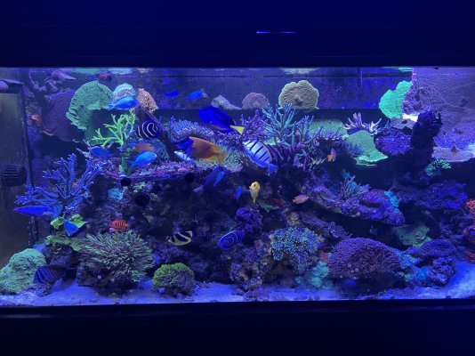
I’m mostly focused on SPS and also like to take risks with non traditional reef safe fish, angels, butterflies, puffers.

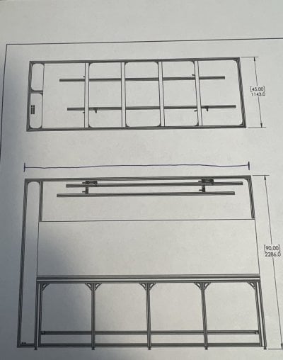
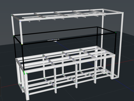
Anyway, this new build will be a 120”x45”x29” Peninsula build.

Here’s a rough 3D rendering I made up to give an idea of what I’m shooting for.
IMG_5047.png

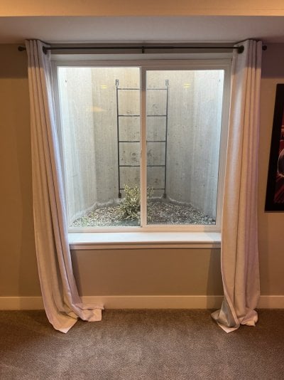
The first major obstacle I’ve had to overcome is that this is going to be placed in a finished basement, and there was absolutely no way to fit a 10’ tank, and a 10’ stand down the basement stairs .
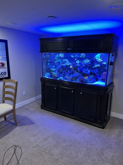
IMG_3890.jpeg IMG_4357.jpeg
It will be positioned so it sticks out lengthways from the backwall into the room like below (before the basement was finished).
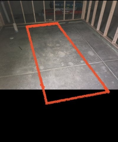
IMG_3379.jpeg

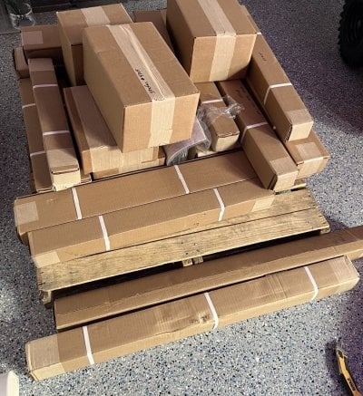
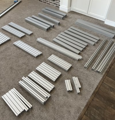
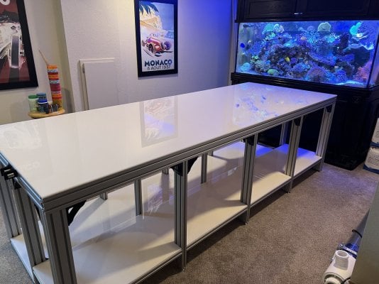
For the stand, it made sense to go with extruded aluminum, it would be easy to move into the basement and assemble on site. I used Controlled Dynamics to build my stand. Russ over there was amazing to work with and highly recommend him and the company/product if you are looking for a top quality stand.
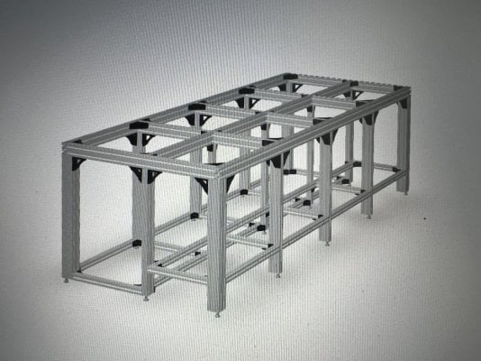
IMG_5078.jpeg

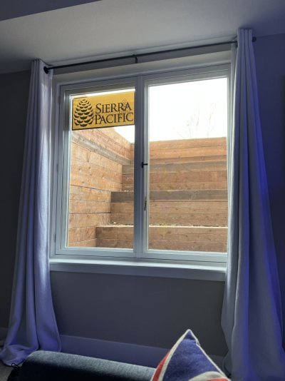
The next problem was how to get the tank down into the basement. I got quotes to build on site and it was about 3X the cost… so I wanted to avoid this. So.. I had an idea. Replace the window and window well in the basement with a French casement window and a terraced window well… managed to sell this idea to the wife, and we actually love the new look.. and it also now allows a 10’ fish tank to slide through the basement window (mathematically speaking).

Finished look.
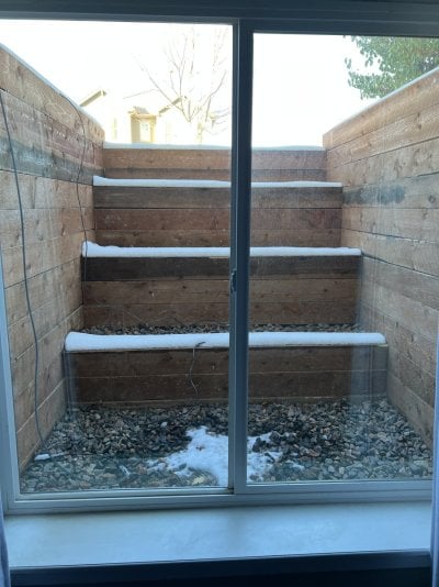
IMG_4704.jpeg

I did some math, and figured out what the levels of the window well needed to be.
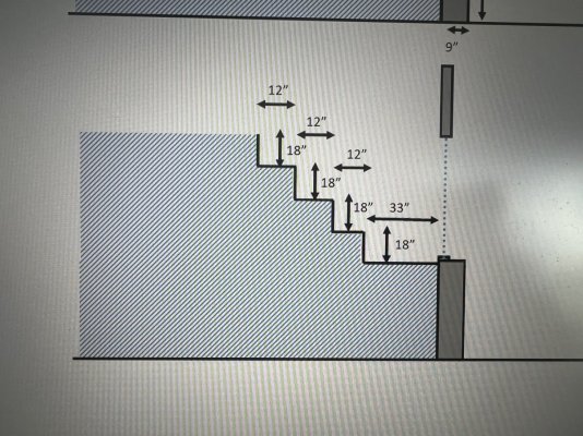
IMG_3774.jpeg

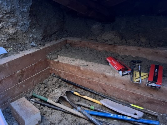
I had a company come in and rip the old concrete window well out.
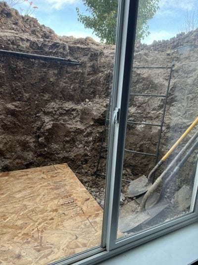
IMG_4558.jpeg

In went the Timbers
IMG_4571.jpeg

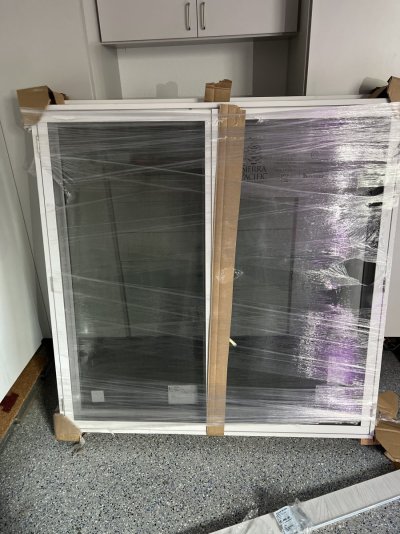
New Double French Casing window…
D0BCBAF8-8516-4DA1-B706-61290E7A887B.jpeg

And the finished product
F2A04F16-9284-45C1-A035-727BCDE1B124.jpeg

Will provide more updates soon.
 

SPR1968

No, it wasn’t expensive dear....
View Badges
Joined
Feb 21, 2017
Messages
20,047
Reaction score
124,743
Location
Nottinghamshire England
Rating - 0%
0   0   0
Following along and keep the pictures coming!
 
OP
OP
iReefer12

iReefer12

Well-Known Member
View Badges
Joined
Apr 22, 2012
Messages
809
Reaction score
700
Location
Boulder, CO
Rating - 100%
1   0   0
Humidity Control
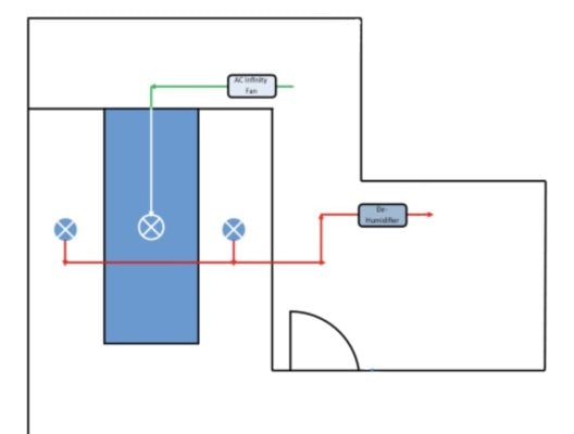
While humidity isn’t too bad in Denver, it is still a major concern for me, and for anyone planning a large tank. The canopy is designed to go all the way to the ceiling, the cabinet doors will have vents in them. So my basic plan is to push air through the canopy, and then duct air from either side of the canopy into a de-humidifier. Like the drawing below.
C4E03CF6-FEF2-40D9-83D0-91DD9A401EFF.jpeg
IMG_4296.jpeg

I’m considering adding another vent to blow air from directly in the canopy out of the house.. but I’d rather not do that tbh.

Anyway, here’s how this step went.
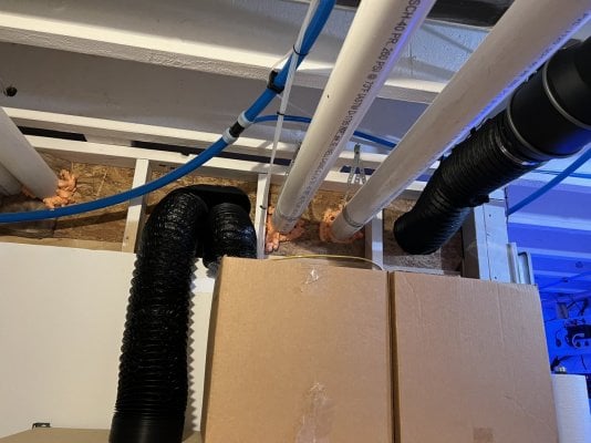
Im going to use the AC Infinity fan to blow air from the mech room into the canopy.
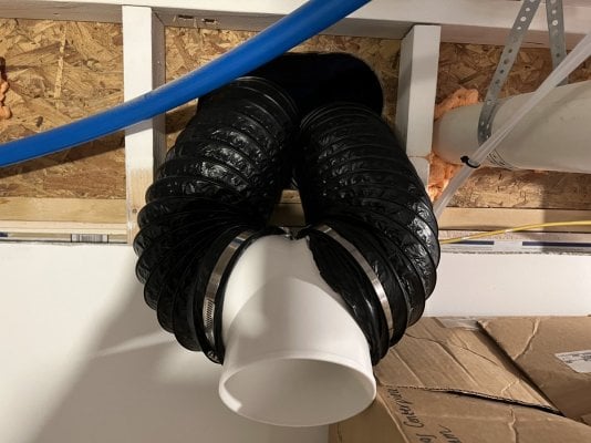
The two ducts go into a Y-connector, and then into the de-humidifier.
IMG_4358.jpeg
IMG_4360.jpeg
 
OP
OP
iReefer12

iReefer12

Well-Known Member
View Badges
Joined
Apr 22, 2012
Messages
809
Reaction score
700
Location
Boulder, CO
Rating - 100%
1   0   0
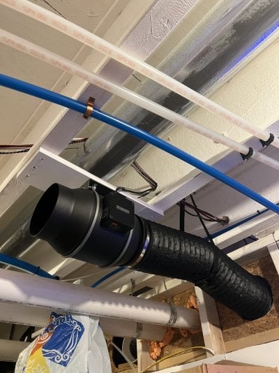
Here’s the AC Infinity fan mounted.
IMG_5780.jpeg

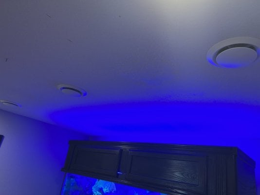
And here’s the 3 vents finished up, so the middle vent is where the AC Infinity fan blows air out of, hoping this pushes the humid air out and then gets sucked out into the De-Humidifier. I hope.

IMG_5781.jpeg
 
OP
OP
iReefer12

iReefer12

Well-Known Member
View Badges
Joined
Apr 22, 2012
Messages
809
Reaction score
700
Location
Boulder, CO
Rating - 100%
1   0   0
Power Management
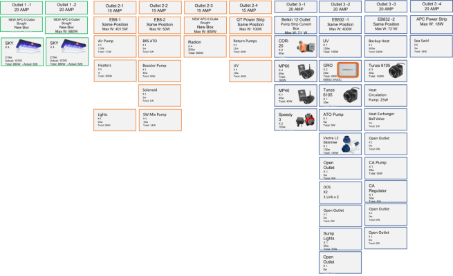
Something that I had to figure out was power management. There'll be a lot of power being used and I wanted to have a coordinated plan to try to minimize risk of overloading a circuit or even an outlet or power strip.

I have 2 dedicated 20 AMP circuits in the fish room, and a non-dedicated 15 AMP circuit.. while initially I thought that would be plenty, with 8 SKY LED's that uses up a lot of available watts. I had an electrician come in and add an extra outlet to one of the 20 AMP circuits and to the 15 AMP circuit, mainly to help help me spread the load out across the EB832's and the various power strips, never do I want to load up too many things to one power strip.

Here's a diagram that will help me as I tackle electrical down the road.

Power Management2.png
 
Last edited:
OP
OP
iReefer12

iReefer12

Well-Known Member
View Badges
Joined
Apr 22, 2012
Messages
809
Reaction score
700
Location
Boulder, CO
Rating - 100%
1   0   0
Heating

With this size of tank, I was desperate to find a way to use the gas water heater method to heat it rather than having a bunch of glass stick heaters in my sump. The goal is somewhat to save money on monthly electricity cost, but also as you saw in the last post, to try to keep the electric load of my outlets as low as I possibly can.

The advantage I have is that my fish room is part of my mechanical room, the access to the gas boiler was very convenient for me.

There’s a couple of threads on here that discuss this process, and even a YouTube video, I can’t think of the User who posted the how to video, but I followed his steps and installed it.


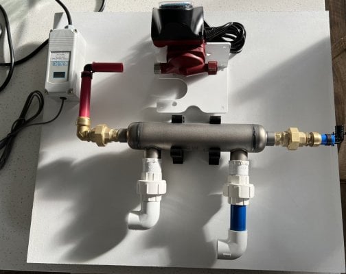
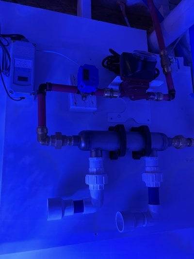
Something I wanted to achieve was to keep all of the components in a compact package and on its own control board. So this is what that looked like.
IMG_4319.jpeg


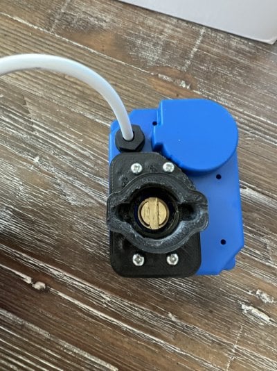
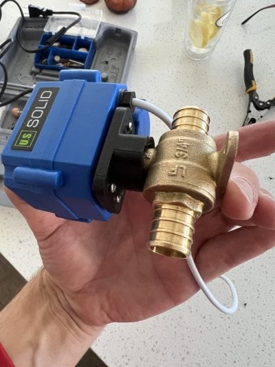
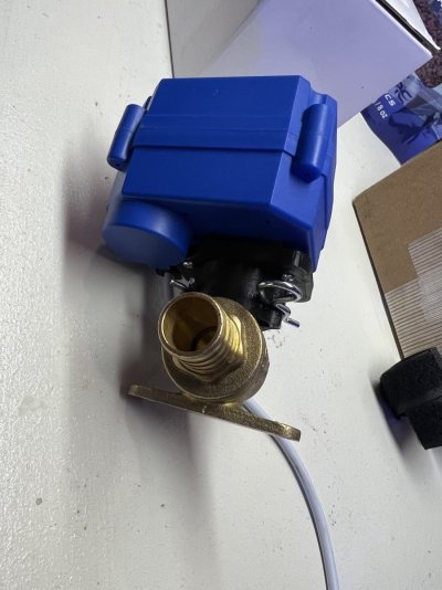
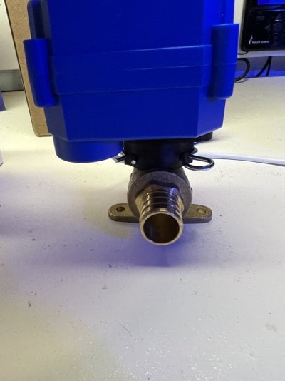
A problem I ran into was that the motorized ball valves all had brass ball valves that contained lead.. I’m approaching everything with an abundance of caution, so while it was possibly fine, I just didn’t want to have in the back of my head every time running hot water that my fish tank project may be causing lead to enter the water my family’s using.. I searched high and low to find a ball motorized ball valve that was lead free… there is nothing out there.

So I utilized the motor from the ball valve people use on this project, and 3D printed a new mounting bracket that will allow it to use a lead-free ball valve from Home Depot.
EAF8EB64-47BE-4770-951C-DB4344E9E8BD.jpeg
IMG_4517.jpeg
IMG_4551.jpeg
IMG_4552.jpeg

I had a plumber come out and hook up the lines to the boiler, it’s now ready to be plumbed into one of the return line when the time comes.

IMG_4566.jpeg
 
OP
OP
iReefer12

iReefer12

Well-Known Member
View Badges
Joined
Apr 22, 2012
Messages
809
Reaction score
700
Location
Boulder, CO
Rating - 100%
1   0   0
Yeah, I’ve seen others just go ahead and use that standard valve, I’m not an expert, so I couldn’t ever find out how bad it would have been to do the same, but I just didn’t want to take any chance. While the reef tank is important, the house and family always are priority, so everything is approached with an abundance of caution.
 
OP
OP
iReefer12

iReefer12

Well-Known Member
View Badges
Joined
Apr 22, 2012
Messages
809
Reaction score
700
Location
Boulder, CO
Rating - 100%
1   0   0
Quarantine
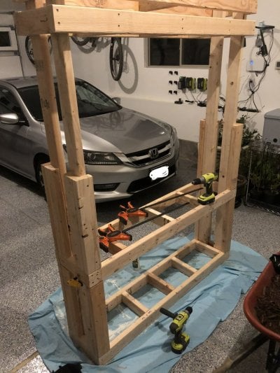
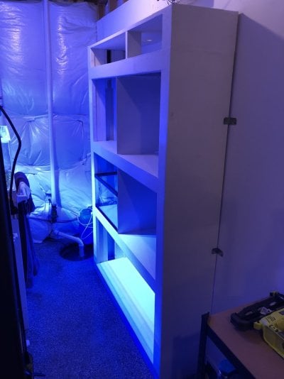
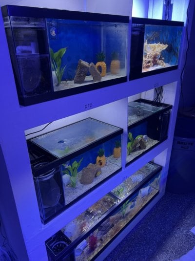
I wanted to make sure there was room to quarantine a decent number of fish at any one time, so building a rack to house multiple QT/Temporary tanks was important.

This rack would house four 15g tanks and one 33g long tank on the bottom rack. I built it using the standard wooden stand instructions, but to accommodate multiple levels.
63202008999__BEC4DA62-F07B-4084-8362-A7E30CA9061C.jpeg

Here’s the finished product.
IMG_0915.jpeg

The very top shelf was to house all the electronics for the Frag tanks.

I couldn’t find a 33g long tank anywhere, by this time I’d already built the shelving unit for this size tank.. I was committed. I found some of the black plastic frames/braces online, and decided to have glass cut and build one myself.

Once that tank was built, I bought the AIO kits off eBay and converted the tanks to AIO’s. They all worked pretty good, and I’ve used them a couple of times already.

IMG_3833.jpeg
 
OP
OP
iReefer12

iReefer12

Well-Known Member
View Badges
Joined
Apr 22, 2012
Messages
809
Reaction score
700
Location
Boulder, CO
Rating - 100%
1   0   0
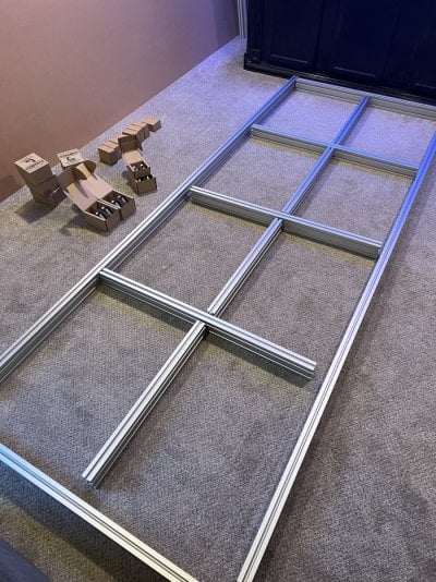
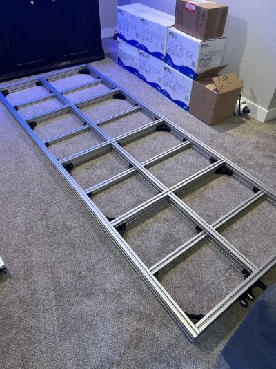
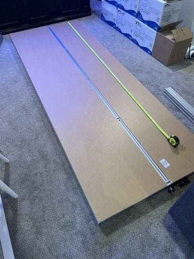
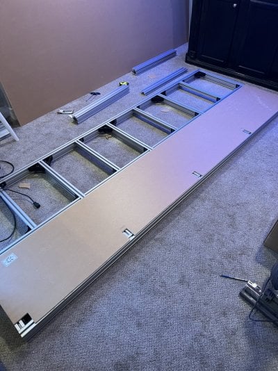
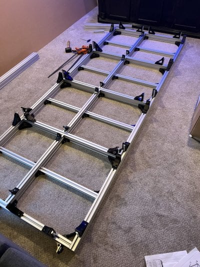
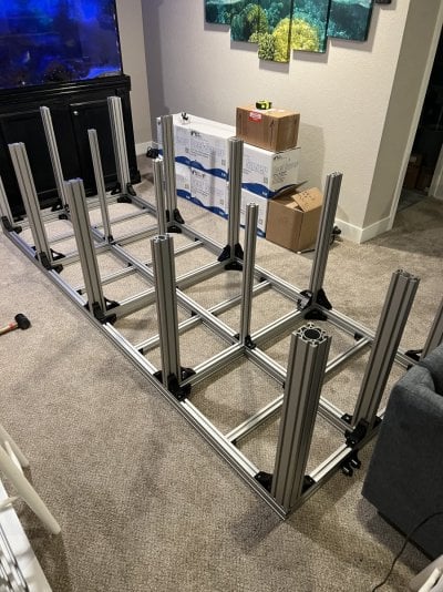
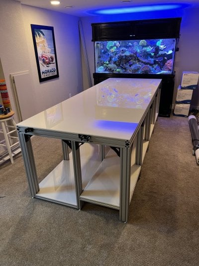
The Stand

Just a big old photo dump of the stand and it’s various stages of assembly.

IMG_5267.jpeg
IMG_5269.jpeg
IMG_5279.jpeg
IMG_5286.jpeg
IMG_5287.jpeg
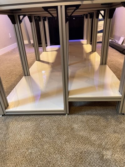
Took this opportunity to cut the acrylic for the lower levels. It made it easy to see where to cut out for the legs etc.
IMG_5301.jpeg
IMG_5307.jpeg IMG_5346.jpeg

And there it is, the stand is assembled.
IMG_5377.jpeg
IMG_5378.jpeg
IMG_5380.jpeg

Really can’t say enough good things about Controlled Dynamics. I wouldn’t say I was skeptical, but it’s hard not to be worried when we’re talking close to 10,000lbs of weight, and I’ve worked with extruded Aluminum before, but this is some next level stuff. The corner brackets have an angled bolt pattern, this applies so much more torque to the joints and it adds a lot more strength than standard bolt patterns, it also helps ensure things get aligned and are square.

The whole stand took perhaps 12hrs to build by myself, and it was really quite fun, like a giant Lego build. If you have any questions on the stand let me know and I’ll do my best to answer them.
 

flagg37

Custom stair builder - TreeofLifeStairs.com
View Badges
Joined
May 28, 2016
Messages
950
Reaction score
1,119
Location
Denver area
Rating - 0%
0   0   0
The Stand

Just a big old photo dump of the stand and it’s various stages of assembly.

IMG_5267.jpeg
IMG_5269.jpeg
IMG_5279.jpeg
IMG_5286.jpeg
IMG_5287.jpeg
Took this opportunity to cut the acrylic for the lower levels. It made it easy to see where to cut out for the legs etc.
IMG_5301.jpeg
IMG_5307.jpeg IMG_5346.jpeg

And there it is, the stand is assembled.
IMG_5377.jpeg
IMG_5378.jpeg
IMG_5380.jpeg

Really can’t say enough good things about Controlled Dynamics. I wouldn’t say I was skeptical, but it’s hard not to be worried when we’re talking close to 10,000lbs of weight, and I’ve worked with extruded Aluminum before, but this is some next level stuff. The corner brackets have an angled bolt pattern, this applies so much more torque to the joints and it adds a lot more strength than standard bolt patterns, it also helps ensure things get aligned and are square.

The whole stand took perhaps 12hrs to build by myself, and it was really quite fun, like a giant Lego build. If you have any questions on the stand let me know and I’ll do my best to answer them.
What’s the reasoning behind having a split level to the bottom of the stand?
 
OP
OP
iReefer12

iReefer12

Well-Known Member
View Badges
Joined
Apr 22, 2012
Messages
809
Reaction score
700
Location
Boulder, CO
Rating - 100%
1   0   0
So I split the levels so that the sump will go on the lower level, and the raised level will have a long shallow Frag tank; I wanted to keep the Frag tank shallow, so needed to raise it up in order to allow it to overflow into the sump.
 
OP
OP
iReefer12

iReefer12

Well-Known Member
View Badges
Joined
Apr 22, 2012
Messages
809
Reaction score
700
Location
Boulder, CO
Rating - 100%
1   0   0
Speaking of Sump, I’m supposed to pick it up next week.

It’s an 8’ acrylic monster.

I contracted Lifereef to build this for me as they are local and I could avoid shipping costs, it’s the biggest (longest) sump he’s ever made, originally he didn’t think he could build it, but he made it work.

Here’s the design, a little unconventional layout, but I think it should work.

IMG_5805.jpeg
 
OP
OP
iReefer12

iReefer12

Well-Known Member
View Badges
Joined
Apr 22, 2012
Messages
809
Reaction score
700
Location
Boulder, CO
Rating - 100%
1   0   0
The cable slits are a great idea. What kind of skimmer setup are you planning to run? Any plans for a fleece roller or have you settled on filter socks?
I’m going to run an external skimmer, the 1.5 bulkhead in the drain chamber will pump directly to the skimmer, and then return in the refugium section.
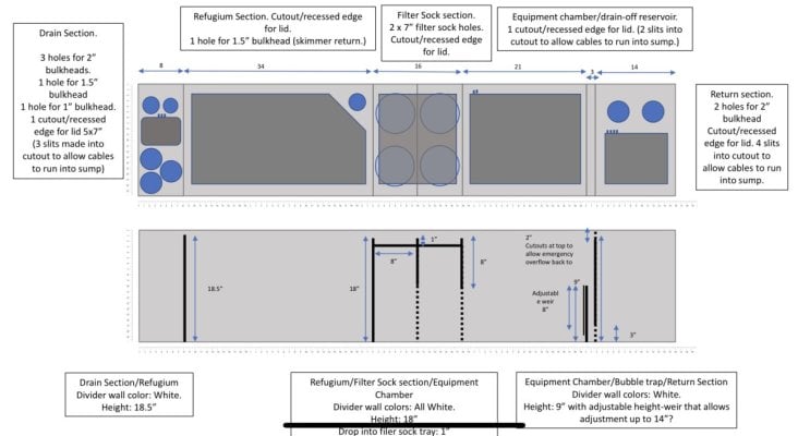
I didn’t want to run a fleece roller, my methodology is keep it simple, so I have the filter socks for when I may need to polish, but realistically I won’t be running filter socks full time.
 

blaxsun

10K Club member
View Badges
Joined
Dec 15, 2020
Messages
26,709
Reaction score
31,149
Location
The Abyss
Rating - 0%
0   0   0
I’m going to run an external skimmer, the 1.5 bulkhead in the drain chamber will pump directly to the skimmer, and then return in the refugium section.

I didn’t want to run a fleece roller, my methodology is keep it simple, so I have the filter socks for when I may need to polish, but realistically I won’t be running filter socks full time.
I figured that was the case with the skimmer (just wanted to clarify). So what will be your main method of filtration then? Skimmer and refugium?
 
OP
OP
iReefer12

iReefer12

Well-Known Member
View Badges
Joined
Apr 22, 2012
Messages
809
Reaction score
700
Location
Boulder, CO
Rating - 100%
1   0   0
I figured that was the case with the skimmer (just wanted to clarify). So what will be your main method of filtration then? Skimmer and refugium?
Yeah pretty much relying on the skimmer to remove large particle stuff, refugium will grow chaeto to remove No3 and Po4.
 

Reefing threads: Do you wear gear from reef brands?

  • I wear reef gear everywhere.

    Votes: 37 15.9%
  • I wear reef gear primarily at fish events and my LFS.

    Votes: 13 5.6%
  • I wear reef gear primarily for water changes and tank maintenance.

    Votes: 1 0.4%
  • I wear reef gear primarily to relax where I live.

    Votes: 30 12.9%
  • I don’t wear gear from reef brands.

    Votes: 135 58.2%
  • Other.

    Votes: 16 6.9%
Back
Top