I'm not using that specific board but I am using essentially the same thing (these ones:
https://www.littlebirdelectronics.com.au/8-channels-5v-relay-module).
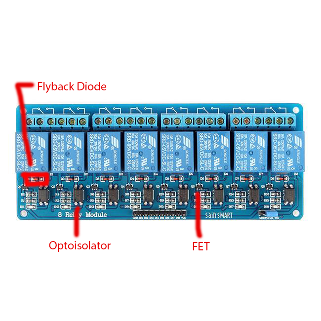
@Ranjib will be able to confirm or not but I believe a few ReefPi users are already using these directly from the Pi with no issues? Currently I am not though, I am powering my 2 relay boards with an LM2596 to step 12V DC down to 5V and I still plan to power them separately going forward so it doesn't matter to me either way.
The ground between the Pi to both the relay boards is the bit that is confusing me haha. Because I am pretty sure I don't currently have a ground between them but they are still working fine (switching on and off when the Pi tells them to that is, I don't have the mains outlets connected yet). Is it a safety thing?
And sorry about the confusion with the diagram, I drew the green and blue cables as a single line just for simplicity, in actual fact the AC cable (green) would have 3 wires in it (live, neutral and earth) and the control cable (blue) would have 8 wires in it (one per relay to go to the Pi). I only drew the V+ and Ground wires (red & black) separately as that is the bit I am confused about.
I do understand that I could do it with only 1 buck converter, however if I did that in addition to the control cable and the mains power cable going to each power board I would also need to have a DC power cable going from the main control unit to each power board. The buck converters are fairly cheap and I will already have AC power going to the power boards so I figured why not just add one to each power board as well to power the relays locally so that I only need 2 cables going to each power board instead of 3. Does that make sense?
I also wasn't sure what amperage I would need if I was to power everything off of 1 supply, where as I know I can power the Pi and then some from a 3A supply and I know that giving each relay a 3A supply is also more than enough so I couldn't see any harm in it.
If it turns out that I do actually need the ground on the relays to go directly back to the Pi then that would bring me back to 3 cables going to each power board anyway so I might as well power the relays from the main control unit. I guess now my main question is why are my relays working fine now when the ground doesn't go back to the Pi?