reef-pi :: An opensource reef tank controller based on Raspberry Pi.

I haven't pulled the trigger on a wavemaker yet, so if this works, it will greatly influence what i buy.

If it does work it should work with any of jebaos even their gyre models. I'm a bit of a ways from testing though.
I'm still working on the temp probe and dosing pumps.

I've spent most of the day today trying to figure out how my second rpi just randomly changed resolution modes. Now that I got that fixed I can get back into the dosing pumps and getting those up and running.
 
If it does work it should work with any of jebaos even their gyre models. I'm a bit of a ways from testing though.
I'm still working on the temp probe and dosing pumps.

I've spent most of the day today trying to figure out how my second rpi just randomly changed resolution modes. Now that I got that fixed I can get back into the dosing pumps and getting those up and running.
I'll be watching...... lol
 
Hello Guys,

Having some issues getting the temperature sensor reading with my Pi Zero W. I had "something" working last night. I was reading three different "temperature" sensors with only one sensor plugged in, and none of them seemed accurate (off by over 12 degrees (f)). It also wasn't working out of the box, but I did something (don't remember what) and was finally able to see it.

So I reformatted the sdcard to try again and still not getting anything read. I have i2c & w1 gpio enabled through the raspi-config. Running the latest 2.0 rc3

My boot.txt looks like:
Code:
pi@reefpi:~ $ cat /boot/config.txt
# For more options and information see
# http://rpf.io/configtxt
# Some settings may impact device functionality. See link above for details

# uncomment if you get no picture on HDMI for a default "safe" mode
#hdmi_safe=1

# uncomment this if your display has a black border of unused pixels visible
# and your display can output without overscan
#disable_overscan=1

# uncomment the following to adjust overscan. Use positive numbers if console
# goes off screen, and negative if there is too much border
#overscan_left=16
#overscan_right=16
#overscan_top=16
#overscan_bottom=16

# uncomment to force a console size. By default it will be display's size minus
# overscan.
#framebuffer_width=1280
#framebuffer_height=720

# uncomment if hdmi display is not detected and composite is being output
#hdmi_force_hotplug=1

# uncomment to force a specific HDMI mode (this will force VGA)
#hdmi_group=1
#hdmi_mode=1

# uncomment to force a HDMI mode rather than DVI. This can make audio work in
# DMT (computer monitor) modes
#hdmi_drive=2

# uncomment to increase signal to HDMI, if you have interference, blanking, or
# no display
#config_hdmi_boost=4

# uncomment for composite PAL
#sdtv_mode=2

#uncomment to overclock the arm. 700 MHz is the default.
#arm_freq=800

# Uncomment some or all of these to enable the optional hardware interfaces
dtparam=i2c_arm=on
#dtparam=i2s=on
dtparam=spi=off

# Uncomment this to enable the lirc-rpi module
#dtoverlay=lirc-rpi

# Additional overlays and parameters are documented /boot/overlays/README

# Enable audio (loads snd_bcm2835)
dtparam=audio=on

#ReefPi Settings
dtparam=i2c_arm=on
dtoverlay=w1-gpio
dtoverlay=pwm-2chan

(I tried specifying the gpio pin also, but it didn't make a difference).

lsmod:
Code:
pi@reefpi:~ $ sudo lsmod
Module                  Size  Used by
bnep                   11981  2
hci_uart               27218  1
btbcm                   8248  1 hci_uart
serdev                  9370  1 hci_uart
bluetooth             366986  24 hci_uart,bnep,btbcm
ecdh_generic           17649  1 bluetooth
brcmfmac              273230  0
brcmutil                9114  1 brcmfmac
snd_bcm2835            23253  0
snd_pcm                89686  1 snd_bcm2835
snd_timer              22428  1 snd_pcm
cfg80211              542402  1 brcmfmac
snd                    60154  3 snd_timer,snd_bcm2835,snd_pcm
rfkill                 21476  6 bluetooth,cfg80211
i2c_bcm2835             6465  1
pwm_bcm2835             3254  0
w1_gpio                 4566  0
wire                   31600  1 w1_gpio
cn                      5687  1 wire
hwmon                  10505  1 wire
uio_pdrv_genirq         3718  0
uio                     9901  1 uio_pdrv_genirq
fixed                   3033  0
i2c_dev                 6674  2
ip_tables              12427  0
x_tables               22130  1 ip_tables
ipv6                  397455  24

Was expecting to see something like:
wire 31600 2 w1_gpio,w1_therm

But that won't show without doing a sudo modprobe w1-therm

Based on the /sys/bus/w1/devices it doesn't appear to be seeing the sensor.

Pic of the breadboard attached.

Any thoughts or something stupid I am overlooking?

IMG_20181118_133813.jpg


Edit: Oh yeah, I get this error:

Nov 18 13:11:45
Failed to initialize i2c. Error:eek:pen /dev/i2c-1: no such file or directory


When I was able to get rid of that error ( messing with the i2c settings in the config based with what I found online) that's when the "three" temp sensors appeared...

Don’t reformat sd card or reinstall reef-pi if something is not working. They are rarely the culprit. Using raspy-config to turn on i2c and one wire. Which guide you are using ? I recommend using the new guides published in adafruit (particularly guide 1 and 3) .
Your wiring looks correct . Did you reboot after configuring everything ? Touch the probe after you hooked it up. And also measure the voltage on the three pins of your probe
 
Dosing controller guide in adafruit is complete, it’s waiting for editorial reviews and probably will be published on Monday or Tuesday.
With this , all the critical documentation is done (7 guides ) . I feel relaxed and can focus on field testing. I think we have most of the things (software bugs, hardware/circuit details) chalked out. Unless there concern I think we are good to go and make 2.0 public release and announcement
 
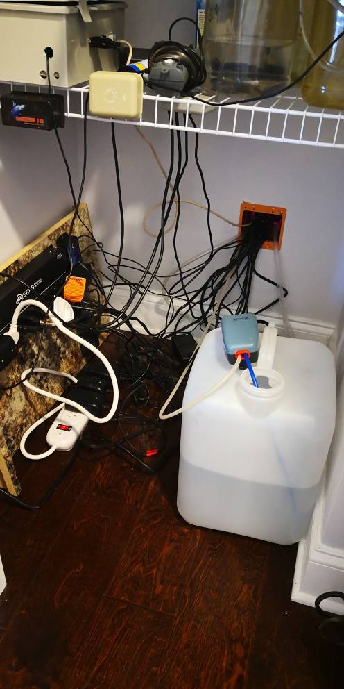
Cleaned up my closet a bit and removed 3 empty DA pc4. Then screwed the reef-Pi outlet bar to the board. I plan a 2nd one just below tthe existing for my 16 outlets So i can remove the white power strip
4b981ba3d1bfb7e59152ea444716f99b.jpg
 
Cleaned up my closet a bit and removed 3 empty DA pc4. Then screwed the reef-Pi outlet bar to the board. I plan a 2nd one just below tthe existing for my 16 outlets So i can remove the white power strip
4b981ba3d1bfb7e59152ea444716f99b.jpg
Very nice :-)
 
Don’t reformat sd card or reinstall reef-pi if something is not working. They are rarely the culprit. Using raspy-config to turn on i2c and one wire. Which guide you are using ? I recommend using the new guides published in adafruit (particularly guide 1 and 3) .
Your wiring looks correct . Did you reboot after configuring everything ? Touch the probe after you hooked it up. And also measure the voltage on the three pins of your probe
Duh, my stupidity got me. This is exactly why you should always measure voltages.

Each of the little +/- banks are isolated from the others. I didn't realize that (my last breadboard didn't have those separations so I wasn't really thinking about it). So there was no voltage to the probe.

Anyways, got it hooked up and now it's reading the sensor and working right!

I am still getting that i2c error though. Any thoughts on that?
Code:
Failed to initialize i2c. Error:open /dev/i2c-1: no such file or directory

IMG_20181118_180639.jpg
 
Duh, my stupidity got me. This is exactly why you should always measure voltages.

Each of the little +/- banks are isolated from the others. I didn't realize that (my last breadboard didn't have those separations so I wasn't really thinking about it). So there was no voltage to the probe.

Anyways, got it hooked up and now it's reading the sensor and working right!

I am still getting that i2c error though. Any thoughts on that?
Code:
Failed to initialize i2c. Error:open /dev/i2c-1: no such file or directory

IMG_20181118_180639.jpg
enable i2c using raspi-config, and reload reef-pi or reboot the whole pi
 
Designing the actual circuit to add it to the rpi is beyond my knowledge but maybe there is a way to hijack their board and have reef-pi control it?
This would also be cool if we could figure out a way to use the Jebao wireless OW series pumps and have the rpi control the with wireless but that might be a bit of a stretch since their wireless capability is just to link the pumps not to control them remotely from a main controller.

I have a Jebao SW2 and I've looked into both controlling it wirelessly via slave mode and controlling it via the input in the controller. I assume the other models are similar. If you search for Jebao in the previous conversations (...somewhere in this thread) you'll find it.

I haven't dug into wirelessly because their system uses a nrf24l01 transceiver and you can't sniff the signals from it. It's possible to wire into the transceiver and record the different signals for emulation but not something I want to dive into.

According to the previous convo, it's possible to build the circuit according to the Kessil light diagram but without the transistors (to bring 10v down to 5v) and use it in the same way - audio cable to Jebao input. Not sure what the other controllers look like but my Jebao input needed to be rewired to use an audio input but that was fairly simple. It worked for on/off control but I didn't test it further (speed, etc). The issue is on the programming side. It's possible to script different waveforms and patterns but it's a big job and not something I'm familiar with.
 
Dosing controller guide in adafruit is complete, it’s waiting for editorial reviews and probably will be published on Monday or Tuesday.
With this , all the critical documentation is done (7 guides ) . I feel relaxed and can focus on field testing. I think we have most of the things (software bugs, hardware/circuit details) chalked out. Unless there concern I think we are good to go and make 2.0 public release and announcement

Very cool.
 
Just tried within raspi-config and rebooted. Still getting error.


That line is in boot/config.txt already.
whats the output of
Code:
ls /dev/
 
whats the output of
Code:
ls /dev/
Code:
pi@reefpi:/dev $ ls
autofs           full       loop2             mmcblk0p2           ram11  ram9     tty1   tty20  tty31  tty42  tty53  tty7       vcs1   vcsa6
block            fuse       loop3             mqueue              ram12  random   tty10  tty21  tty32  tty43  tty54  tty8       vcs2   vcsm
btrfs-control    gpiochip0  loop4             net                 ram13  raw      tty11  tty22  tty33  tty44  tty55  tty9       vcs3   vhci
bus              gpiomem    loop5             network_latency     ram14  rfkill   tty12  tty23  tty34  tty45  tty56  ttyAMA0    vcs4   watchdog
cachefiles       hwrng      loop6             network_throughput  ram15  serial1  tty13  tty24  tty35  tty46  tty57  ttyprintk  vcs5   watchdog0
char             i2c-1      loop7             null                ram2   shm      tty14  tty25  tty36  tty47  tty58  uhid       vcs6   zero
console          initctl    loop-control      ppp                 ram3   snd      tty15  tty26  tty37  tty48  tty59  uinput     vcsa
cpu_dma_latency  input      mapper            ptmx                ram4   stderr   tty16  tty27  tty38  tty49  tty6   urandom    vcsa1
cuse             kmsg       mem               pts                 ram5   stdin    tty17  tty28  tty39  tty5   tty60  vchiq      vcsa2
disk             log        memory_bandwidth  ram0                ram6   stdout   tty18  tty29  tty4   tty50  tty61  vcio       vcsa3
fb0              loop0      mmcblk0           ram1                ram7   tty      tty19  tty3   tty40  tty51  tty62  vc-mem     vcsa4
fd               loop1      mmcblk0p1         ram10               ram8   tty0     tty2   tty30  tty41  tty52  tty63  vcs        vcsa5
 
Code:
pi@reefpi:/dev $ ls
autofs           full       loop2             mmcblk0p2           ram11  ram9     tty1   tty20  tty31  tty42  tty53  tty7       vcs1   vcsa6
block            fuse       loop3             mqueue              ram12  random   tty10  tty21  tty32  tty43  tty54  tty8       vcs2   vcsm
btrfs-control    gpiochip0  loop4             net                 ram13  raw      tty11  tty22  tty33  tty44  tty55  tty9       vcs3   vhci
bus              gpiomem    loop5             network_latency     ram14  rfkill   tty12  tty23  tty34  tty45  tty56  ttyAMA0    vcs4   watchdog
cachefiles       hwrng      loop6             network_throughput  ram15  serial1  tty13  tty24  tty35  tty46  tty57  ttyprintk  vcs5   watchdog0
char             i2c-1      loop7             null                ram2   shm      tty14  tty25  tty36  tty47  tty58  uhid       vcs6   zero
console          initctl    loop-control      ppp                 ram3   snd      tty15  tty26  tty37  tty48  tty59  uinput     vcsa
cpu_dma_latency  input      mapper            ptmx                ram4   stderr   tty16  tty27  tty38  tty49  tty6   urandom    vcsa1
cuse             kmsg       mem               pts                 ram5   stdin    tty17  tty28  tty39  tty5   tty60  vchiq      vcsa2
disk             log        memory_bandwidth  ram0                ram6   stdout   tty18  tty29  tty4   tty50  tty61  vcio       vcsa3
fb0              loop0      mmcblk0           ram1                ram7   tty      tty19  tty3   tty40  tty51  tty62  vc-mem     vcsa4
fd               loop1      mmcblk0p1         ram10               ram8   tty0     tty2   tty30  tty41  tty52  tty63  vcs        vcsa5
ok, i2c-1 is present. Then reef-pi should not complain about it being absent. Lets check how you running reef-pi., What is the out put of this, this will restart reef-pi and we'll see what happens once it comes up.
Code:
sudo systemctl restart reef-pi.service
journalctl -fu reef-pi.service
Question, how you installed and started reef-pi? and what version you are using?
 
Can I ask, I have mars aqua leds 165w x4 all stripped down so modding them I'm not worried about, but if I want to pwm them properly how could I do it? The panels themselves contain 55 3w leds, I have 4 panels, so a total led count of 220 3w leds.

Now there split into 2 channels per panel, white and blue channel, blue channel uses 27 leds 3w each, white channel 28 leds 3w each, it uses 8 drivers that have manual dimming.

Now I'm thinking to replace how there powered by a better system than supplied so they can then be fully controlled by reef-pi via pwm and timers from the pi.

I've been researching some but it's very confusing on the power side of things, has anyone done anything like this? Or any advice about powering a strip of 108 blue 3w leds and pwm and a strip of 112 mixed white channel leds 3w.

Is it even possible to power and pwm so many leds in series?
Is the manual dimmer something like this?
20171111_195957 - Copy.jpg
This is the circuit that has been working for my SBReefLights with Reef-Pi control.
Custom Dimming Circuit Updated.jpg

It is plug and play into the system and uses the 12V from the light system, so all you need to send is signal and GND.
 
Is the manual dimmer something like this?
20171111_195957 - Copy.jpg
This is the circuit that has been working for my SBReefLights with Reef-Pi control.
Custom Dimming Circuit Updated.jpg

It is plug and play into the system and uses the 12V from the light system, so all you need to send is signal and GND.
I have been looking into this as well. Mars Aqua use 0-10v analog dimming . The dimmer is different than that ( on mine at least) They have VDM connection but this wiring should work.
 

TOP 10 Trending Threads

Back
Top
Home
Post thread…
Market
What's new