



reef-pi :: An opensource reef tank controller based on Raspberry Pi.

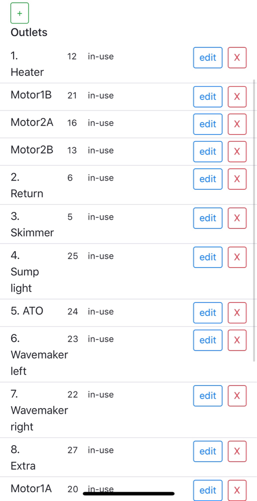
This is kind of nitnoy not important. But is there a way to order the connectors list. I was doing 1., 2., 3., etc which only works till 9. The motor lines for some reason appear where ever they want no matter what I name them. Not super important. Just helps me keep equipment organized.
aea64b2e8e11d4d9f5ab6c032c3a84fb.jpg

Try numbering them 01, 02, 03, etc. Without the zero in front of your single digits, 10 is seen as the number after 1, 20 would be seen as the number after 2 and so on.
 
Try numbering them 01, 02, 03, etc. Without the zero in front of your single digits, 10 is seen as the number after 1, 20 would be seen as the number after 2 and so on.

Its strange, the "motor" connectors appear wherever they want regardless of what you name them. Its not a big deal just my OCD kicking in lol

@Ranjib are there any future plans to create a dashboard/graph/log for doser use?
 
Last edited:
Its strange, the "motor" connectors appear wherever they want regardless of what you name them. Its not a big deal just my OCD kicking in lol

@Ranjib are there any future plans to create a dashboard/graph/log for doser use?
Yeah, I have to come up with some ideas around this. Exactly what you would like to see? Its a timer + duration + speed thing
 
Its strange, the "motor" connectors appear wherever they want regardless of what you name them. Its not a big deal just my OCD kicking in lol

@Ranjib are there any future plans to create a dashboard/graph/log for doser use?
https://github.com/reef-pi/reef-pi/pull/648
So, all items will be listed in order they were created... not draggable.. but at least its not random.
 
Right, here goes. I am no wiring genius!

I am going to get started on a Reef-pi build but going to do it step by step (ato, power control, temp control to follow) as Im Reefing on a tight budget although not sure that is possible! ££££$$$$$

First step is to convert my two channel blue/white led light (until I can afford a better light setup) into timer controlled by adding 2x 12v relays after the power supply. There are three wires to the lamp from the power supply to the lamp. Im assuming a wire for each channel and a common ground?

Any guidance on what initially I need to procure and how best to wire it would be much appreciated. Not 100% sure that this is the correct relay?

Many thanks
Toby

- Raspberry Pi Zero WH (with pre-soldered header)
https://thepihut.com/collections/raspberry-pi/products/raspberry-pi-zero-wh-with-pre-soldered-header
- 5V 3A Micro USB Mains Power Supply 3 Pin for Raspberry Pi
- 2 channel 12v relay
relay.JPG
- SD Card
- Jumper wires
- Project box
- Pair of IP65 3pin wired plug/socket to match the connectors . (Save cutting the existing cable)


My light but its a 900mm long one.

Stretch Lamp.JPG
This looks good to me. Keep us posted
 
Yeah, I have to come up with some ideas around this. Exactly what you would like to see? Its a timer + duration + speed thing

I think the most important part for me would be to be able to see a record of times the pump was active. Right now I am not at home playing with the doser timer and I have no idea if the pump came on at my set time or not. Maybe something like the CPU graph but in a square wave so to speak that shows times on and for how long then maybe a separate line like the memory graph that shows speed or maybe the height of the on time could be speed? .
 
Just wanted to say thanks to all that contribute to this project, although my reef is small it really gives me a peace knowing i get text with issues and it make the everyday much easier, sometime i'll trust it to dose but really fear a mechanical relay failure on the closed "on" position. Thinking I may daisy chain 2 relays so if one failed on, the other would be open.

A couple shots, frags starting to color encrust. Tyree undata (from my old tank that was tore down 10+ years back), JF flame started as just a tiny nub, and RR grape juice, purple sescale. That is a garf bonsai very browned out rescue piece behind the undata. Yep kinda like the older stuff.
grape.JPG jf flame.JPG undata.JPG grape.JPG jf flame.JPG undata.JPG
 
I think the most important part for me would be to be able to see a record of times the pump was active. Right now I am not at home playing with the doser timer and I have no idea if the pump came on at my set time or not. Maybe something like the CPU graph but in a square wave so to speak that shows times on and for how long then maybe a separate line like the memory graph that shows speed or maybe the height of the on time could be speed? .
I haven't gotten to dosers yet but similar to what the thermostat and heater graph look like?
 
Try numbering them 01, 02, 03, etc. Without the zero in front of your single digits, 10 is seen as the number after 1, 20 would be seen as the number after 2 and so on.
Mine annoys me too. I am more simple but the are numbers as "powerbar-outlet#". they do not go in order and it frustrates me.
outlets.JPG
 
Just wanted to say thanks to all that contribute to this project, although my reef is small it really gives me a peace knowing i get text with issues and it make the everyday much easier, sometime i'll trust it to dose but really fear a mechanical relay failure on the closed "on" position. Thinking I may daisy chain 2 relays so if one failed on, the other would be open.

A couple shots, frags starting to color encrust. Tyree undata (from my old tank that was tore down 10+ years back), JF flame started as just a tiny nub, and RR grape juice, purple sescale. That is a garf bonsai very browned out rescue piece behind the undata. Yep kinda like the older stuff.
grape.JPG jf flame.JPG undata.JPG grape.JPG jf flame.JPG undata.JPG
Thank you. Sps Looks very nice. Can’t wait till they grow out :-) . Keep us posted
 
Mine annoys me too. I am more simple but the are numbers as "powerbar-outlet#". they do not go in order and it frustrates me.
outlets.JPG
I just pushed a change that will sort them by their creation order. Is it make sense to order them by name ?
 
I haven't gotten to dosers yet but similar to what the thermostat and heater graph look like?
Yeah, I think I have some idea now. Let’s wait till 2.0 is out of the door , may be 2.1
 
Thanks Ranjib, is that the correct type of relay? Any tips for a newbie how to wire it up please?
Very easy to hook up to the pi. vcc is the power pin, it will connect to the pi's 3.3v pin, gnd is ground, it will hook up to a ground pin on the pi. in1 and in2 are the signal connections, they will hook up the gpio pins that you choose to select via software to control each relay. These are the same connections no matter if you have a single, 2 channel or 8 channel relay, just more gpio pins are used the more relays you are controlling. https://learn.adafruit.com/users/ranjib If you haven't already found this guide, start here to get a better understanding of the workings.
 
I just pushed a change that will sort them by their creation order. Is it make sense to order them by name ?
I prefer name Here because it helps me keep the back end (config tab) straight. on the front, I use the vanity names of the device.
 
Thanks Ranjib, is that the correct type of relay? Any tips for a newbie how to wire it up please?
Those relays can control most AC equipment across the globe . But they need 12v, how you plan to power the pi? We need your full bill of materials
 

ARE YOU READY TO CONFESS TO CRAZIEST, DUMBEST, FUNNIEST THING YOU’VE EVER DONE IN REEFING?

  • Yeah, I'll confess! (Share your story in the comments!)

    Votes: 33 54.1%
  • Nah, I'll keep mine a secret...(Don't be like that, share with the class!)

    Votes: 28 45.9%
Back
Top
Home
Post thread…
Market
What's new








