reef-pi :: An opensource reef tank controller based on Raspberry Pi.

It’s amazing how many connector issues we experience . This probably the biggest pain point across all the threads. So simple but still so failure prone :-/
Standardization is a big help in these sorts of issues, but that is counter to the open source methodology. @theatrus seems to be on the right track these days with connectors, and the big help is putting a bunch of stuff on one PCB, which removed the need for lots of wires and connectors everywhere.

I see reef-pi as having a three tiered level system. First tier is the Base Board and the like, all you have to do is a bit of screwing things together, and perhaps soldering the temp sensor will become unnecessary soon ;). Most everything else just plugs into the board as is, really easy for someone slightly familiar with linux and hardware in general.

Tier two is being able to follow guides, and build your own machines with custom capabilities. You have many more wiring and connector issues with this tier but it is great because it is cost effective and super flexible for a given set of needs/wants.

Tier three is, uh, @Ranjib @theatrus and a few others here that I won't name because I don't want to forget anyone! More or less, experts that have a broad and deep understanding of these types of systems and can help guide the Tier 2 folks with their projects and are generally the shepherds of the the whole concept.

I bring this up because it helps set expectations. Might help with folks understanding what it takes to get to tier two, and making the commitment to the time to understand a bit deeper rather just jumping in and winging it. (And then asking silly questions in the megathread like me!)

 
As a hobbiest its difficult and expensive to have the proper tools to do the more reliable connectors. For the jst-xh on my hat board, I ordered premade pigtails and solder and tape/heatshrink them to the pigtail of the other type connector I need. Not worth investing in an expensive crimp tool, and the cheaper crimp tools are a big crapshoot.
I use ethernet jacks because I have good tools to make them. In the end, I like good old screw terminals but size become an issue.
So yes, you are right, connectors can be a trouble spot, and the first place to look when something doesn't work as planned.
Always check grounding first, right?! It's amazing how many times it's a grounding issue. Reference points are important, in all aspects of life :)
 
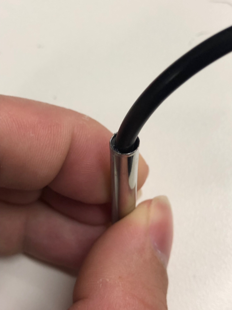
I’ve been buying various 1 wire probes to find a good source. Latest ones are a bit weird:

- the metal is actually stainless this time
- there is no visible potting seal at the cable entrance.

I need to whip out a power tool to cut these apart to see if there is potting deeper inside or not, as the metal is actually stainless now.

Always cut away the heatshrink on these - it’s not going to form a watertight seal anyway.

312defbeacf708985dbbce4767b4c9a8.jpg
 
I’ve been buying various 1 wire probes to find a good source. Latest ones are a bit weird:

- the metal is actually stainless this time
- there is no visible potting seal at the cable entrance.

I need to whip out a power tool to cut these apart to see if there is potting deeper inside or not, as the metal is actually stainless now.

Always cut away the heatshrink on these - it’s not going to form a watertight seal anyway.

312defbeacf708985dbbce4767b4c9a8.jpg
@theatrus
I bought 2 drok branded before Xmas that are fantastic. 12 dollars for 2 3m probes. Real high temp silicone insulation. Double crimped. Real Stainless, the wire was shielded. ALAS, they ran out and no more to be had. I work in industrial settimg and these are industrial quality!
The last one from Drok looks like the one in your picture...disappointing, but its going to be my ambient air temp sensor.
20190103_004315.jpg
 
Good troubleshooting is just a logical orderly process of elimination!
It's so easy to assume that it is some weird second order effect, but it comes down to continuity between points usually. In other words, it's hard for me to start with the easy and obvious. My mind goes straight to a really odd part failure or something instead.
 
@theatrus
I bought 2 drok branded before Xmas that are fantastic. 12 dollars for 2 3m probes. Real high temp silicone insulation. Double crimped. Real Stainless, the wire was shielded. ALAS, they ran out and no more to be had. I work in industrial settimg and these are industrial quality!
The last one from Drok looks like the one in your picture...disappointing, but its going to be my ambient air temp sensor.
20190103_004315.jpg

Yeah these looks really nice.

I’ve gotten some that were epoxy filled or capped and a flat bottom pill, but the steel wasn’t very stainless. All of these sensors are super cheap though, just wondering if it’s the labor effort to fix them vs using a better one (e.g. the SparkFun one)
 
context?? is this here in r2r thread?
I still have yet to start of the beginning of this thread...Work has been crazy with xmas holiday and now
valentines day is around corner...It is on my MUST READ list...just skimming other people's build threads
to see if my goals are possible and is there a shopping list??

I do have tons of questions after all reading so far...Can I ask her or do i need to do somewhere else?
thanks in advance
 
Yeah these looks really nice.

I’ve gotten some that were epoxy filled or capped and a flat bottom pill, but the steel wasn’t very stainless. All of these sensors are super cheap though, just wondering if it’s the labor effort to fix them vs using a better one (e.g. the SparkFun one)
I may poke around industrial sites looking for something similar to those 2...who knows, they may be decently priced
 
Last edited:
I didn't get everything I wanted to get done today due to the 12+inches of snow on the ground, heavy wet snow. Have about half the driveway left to do, anyone want to lend a hand? ;)

I did get my reef-pi mounted and the temp probes are in the tanks, so I did make some progress, will have some pictures tomorrow on the installation, more wire management kungfu left to do. :)

DeepinScreenshot_select-area_20190112202511.png
 
Can someone provide more information regarding the lighting pwm configuration. I am currently using the rpi pwm circuits and was playing around with the auto setting to simulate sunrise/sunset but trying to understand what I am seeing. I have the settings to come on at 10am @ 10% then @12 go to 30% then @2 go to 45% and then ramp down from there.

What I see though is its 10:48 local time and it appears that if I turn off the 10am setting it doesn't go off, it appears to be using the 12pm setting, if I set the 12pm setting to 0 then it stays on the 10am setting unless its 0 then its off. Basically in order to turn it off you have to have both the 10am and 12pm setting set to 0. Maybe its ramping up from the 10am to the 12pm setting, so from 10% to 30%.

I did a search and tried to find more detailed information concerning the light auto setting but just havn't found the information that explains how it works.

Nevermind I found it in the adafruit guides:
reef-pi linearly increments/decrements the PWM values in between the two-hour intervals. This is an effective way to simulate the daylight cycle with finer control over how steep the PWM value ramp up/down will be.
:)
 
@Ranjib
I have a question on the temperature controller. Fooling around with it, I take it there is no hysteresis setting yet?
For example if you set it at 78, the heater goes on above 78 and goes off below 78?
I recall that a hysteresis band may be a 3.0 feature?

As an example there are 2 different ways your home thermostat works to keep the house temps steady.
One method is your thermostat has a hysteresis or "swing" setting. To prevent your furnace from cycling too fast if you set the temp at 78, with a hysteresis of 1 degree, the furnace will run until it is 78 degrees and shut off, and not come back on until the temp drops 1 degree below 78. Smaller swing settings mean the heat cycles more often, larger swing settings make it cycle less often but with more of a temperature swing.

The second method a home t-stat can prevent short cycling is by using a cycles per hour method. If you set the cycles per hour to lets say 6, and thr temperature to 78, every ten mins the tstat checks to see if its below 78, and will run the furnace until it hits the target and shut down. More cycles per hour means a steadier temp, but too many cycles per hour cause the furnace to short cycle and turn on and off too much.

For anyone interested, reef pi already has a cycles per hour method. It can be set up by how often the temp controller checks the temperature!
If you set reef pi temp controller to 78 degrees, and check temperature every 5 seconds, it will read temp every 5 seconds and turn on the heater when it drops below 78, and turn it off when it reads above 78. The longer the check temp interval is set, the less often the heater runs but it will have a longer run time, and you will get a greater temperature swing . The shorter you set the check temp interval, the heater will run more often, but for shorter run times and keep the temperature steadier. No one wants the heater clicking on and off once a second, so this setting can be fine tuned to your specific tank and heater combo.
 
Can someone provide more information regarding the lighting pwm configuration. I am currently using the rpi pwm circuits and was playing around with the auto setting to simulate sunrise/sunset but trying to understand what I am seeing. I have the settings to come on at 10am @ 10% then @12 go to 30% then @2 go to 45% and then ramp down from there.

What I see though is its 10:48 local time and it appears that if I turn off the 10am setting it doesn't go off, it appears to be using the 12pm setting, if I set the 12pm setting to 0 then it stays on the 10am setting unless its 0 then its off. Basically in order to turn it off you have to have both the 10am and 12pm setting set to 0. Maybe its ramping up from the 10am to the 12pm setting, so from 10% to 30%.

I did a search and tried to find more detailed information concerning the light auto setting but just havn't found the information that explains how it works.

Nevermind I found it in the adafruit guides:
reef-pi linearly increments/decrements the PWM values in between the two-hour intervals. This is an effective way to simulate the daylight cycle with finer control over how steep the PWM value ramp up/down will be.
:)
You beat me to the punch!
 
So I have been successfully using reef pi since the start of November. Mainly the temp and Lighting PWM function. I ran into an issue today that has me wondering about the limitation of the PCA9685 board. I run 3 boards, one for each light fixture. They are equipped with a ldd mean well 1000mA (blues), 1000mA(Whites), and a 700mA(UV/Violets). Each board has jumpers to enable the PWM function of the ldd driver. I use a total of 9 pins from the PCA board, all works great until I go 80% on my blues, 60% on my whites, and 80 on my UV/Violets. The entire system dims to almost in half on every pwm output (visually, since the system status in terminal shows whats set in the UI of reef pi). I can pull all 9 jumpers and 100% on every channel without issue. I am only using the PWM portion of thePCA9685. I did validate that I can run a 80/60/80 on two lights and the last one at a 80/10/80 without loss but anything higher on the last one starts to dim the rest of the system.

Any ideas? I have also played with the frequency with stop and start command in the terminal after to make sure its getting a fresh start after hitting update int he UI.
 

TOP 10 Trending Threads

ARE YOU READY TO CONFESS TO CRAZIEST, DUMBEST, FUNNIEST THING YOU’VE EVER DONE IN REEFING?

  • Yeah, I'll confess! (Share your story in the comments!)

    Votes: 26 56.5%
  • Nah, I'll keep mine a secret...(Don't be like that, share with the class!)

    Votes: 20 43.5%
Back
Top
Home
Post thread…
Market
What's new