

- Joined
- Jul 7, 2017
- Messages
- 106
- Reaction score
- 68
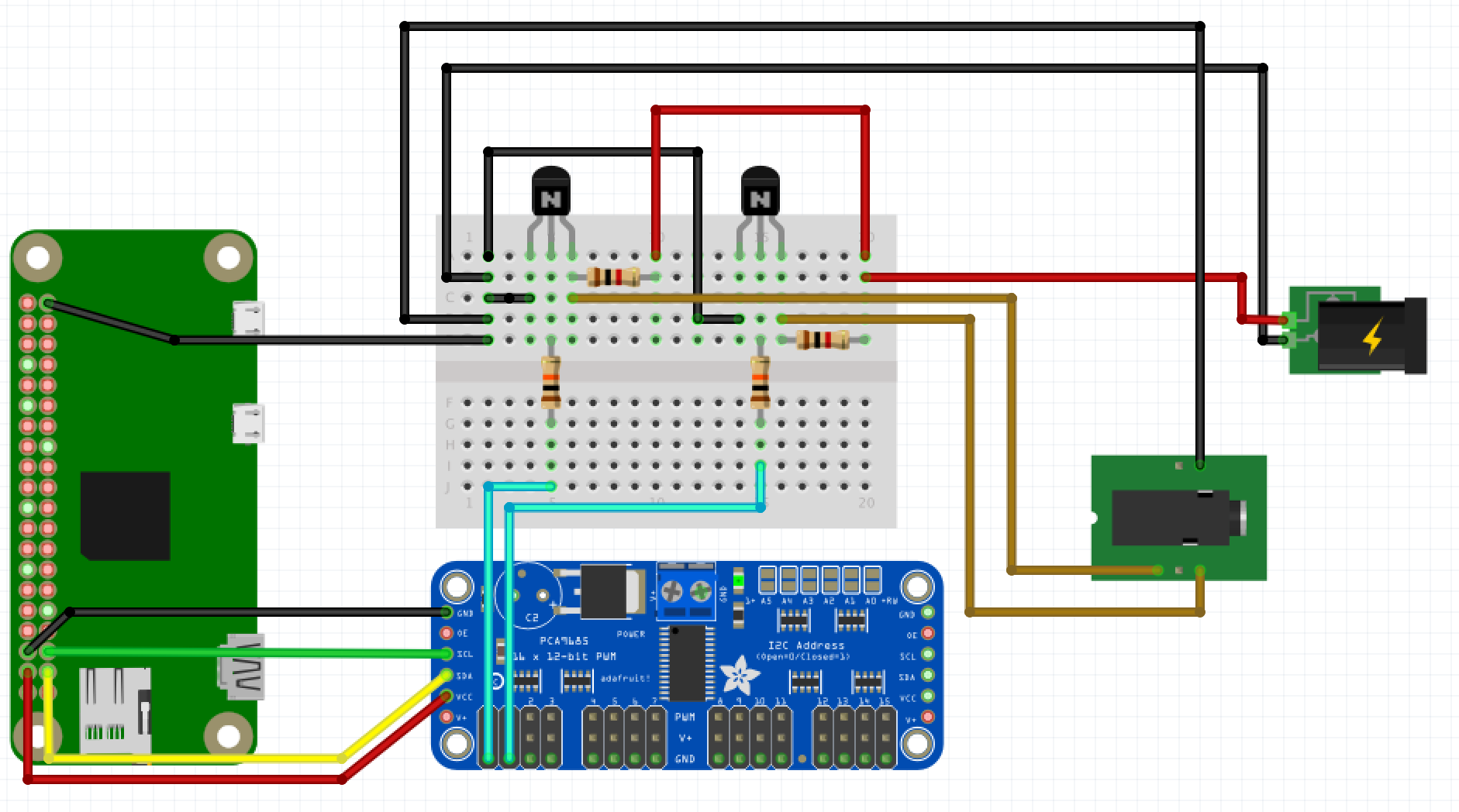
Re-reading over the 193 pages of posts, it looks like 4 people have tried the black box leds with varying degrees of success. Did anyone ever figure out how to get them to dim/ramp without buzzing noises, and smoothly go between values on the reef pi slider? Here are pictures of my black box leds. I can't tell if people are sending the vdim+ / - signals from the pca9685 digitally or with an analog converter. Do we have a fritz diagram for the black boxes with 4 wires? Did we decide we need a 12 volt or 10 volt power supply, and does it require a voltage regulator to drop from 12 to 10. The black box posts are very confusing. Please help.
Thanks!!!


Thanks!!!