reef-pi :: An opensource reef tank controller based on Raspberry Pi.

You have to setup two factor authentication first. Then you can generate the app password like that.
I strongly recommend setting up two factor authentication, as its a serious security problem if you use your actual gmail password, and if reef-pi is compromised your entire account is compromised. I always use it, so I have never tried directly using my password. I think if two factor is not enabled, you can just use your own gmail password, but I dont know if it will work and i would not recommend doing this other than for testing


Thanks I just changed all my passwords and did it that way thanks works great

 
Right now, just trying to follow the steps in the documentation. I’m on the second test. Not working with a regular LED. I’ve uploaded all the pics you’ve asked for already. That’s where I’m at and where I’d like to get past for this next step so that I am confident it is working correctly. So...
Probably and that’s why I was asking your to create a dedicate dthresd so it’s easy to tack. I need the led circuit , and voltage measurement, jack configuration in ui and logs ,,,
 
I wish you had a build thread.
Since I'm on a documentation roll today, I added some info about my reef-pi / home assistant controller setup on github here: https://github.com/sfgabe/home_assistant/wiki/Custom-Home-Assistant-Config-with-Reef-Pi

I don't recommend diving into home assistant for something like this if you're not prepared to put in a ton of work (the dev schedule creates "breaking changes" on a regular basis) and learning a very frustrating coding language (yaml), but once it's working it's pretty cool. And since I've put way too much time into it already I wanted to show it off :)

Again, thanks to @Ranjib and others, especially for a very useful API integration.
 
Meanwhile , field testing is in full steam . Double checking dosing pump output , for me 100% speed, 10 second is 5 ml

FBCB0662-7B18-421C-983E-8997EB51EC68.jpeg


A67C9008-9ECC-491F-BF8B-64D1362756DF.jpeg


32BF06B7-6465-4638-8E69-EEA26D5A2C5F.jpeg
 
I understand. Jebao pp8 or such ( previously rw…) use 12v as power supply and have individual controller. I got no clue how the controller works though.
I think we need to get the code written to use pwm to control these. I believe they use 5v pwm and either a 12v or 24v power input. I'm trying to wrap my head around it with some other code and have a friend who is more knowledgeable working on it.

We have the equipment and everything already in our reef-Pi.
 
I think we need to get the code written to use pwm to control these. I believe they use 5v pwm and either a 12v or 24v power input. I'm trying to wrap my head around it with some other code and have a friend who is more knowledgeable working on it.

We have the equipment and everything already in our reef-Pi.

That would be cool.
I have one of the old RW 10 models that died and was playing around with the controller and the power supply is 24v and from what I can tell the pwm control is 5v.
I was thinking that it wouldn't be to hard to use the pwm built into the rpi and declare the jacks to the pumps as lights. Then you might be able to have some control over the on and of functions and some ramping speed without any programing involved.

Additional programing would be needed in reef-pi to replicate the functionality of the Jebao built in wave modes and feed function.

Designing the actual circuit to add it to the rpi is beyond my knowledge but maybe there is a way to hijack their board and have reef-pi control it?
This would also be cool if we could figure out a way to use the Jebao wireless OW series pumps and have the rpi control the with wireless but that might be a bit of a stretch since their wireless capability is just to link the pumps not to control them remotely from a main controller.

A simple slow ramp up and down using the same control as a lighting schedule would be cool. That way you could run 2 pumps, one on each side of the tank and have them ramp up and down opposite of each other throughout the day and then have them both ramp down to say 20 or 30 percent after lights out.

Just some thoughts for those with more knowledge about circuit construction and programing.

IMG_4511.JPG
 
That would be cool.
I have one of the old RW 10 models that died and was playing around with the controller and the power supply is 24v and from what I can tell the pwm control is 5v.
I was thinking that it wouldn't be to hard to use the pwm built into the rpi and declare the jacks to the pumps as lights. Then you might be able to have some control over the on and of functions and some ramping speed without any programing involved.

Additional programing would be needed in reef-pi to replicate the functionality of the Jebao built in wave modes and feed function.

Designing the actual circuit to add it to the rpi is beyond my knowledge but maybe there is a way to hijack their board and have reef-pi control it?
This would also be cool if we could figure out a way to use the Jebao wireless OW series pumps and have the rpi control the with wireless but that might be a bit of a stretch since their wireless capability is just to link the pumps not to control them remotely from a main controller.

A simple slow ramp up and down using the same control as a lighting schedule would be cool. That way you could run 2 pumps, one on each side of the tank and have them ramp up and down opposite of each other throughout the day and then have them both ramp down to say 20 or 30 percent after lights out.

Just some thoughts for those with more knowledge about circuit construction and programing.

IMG_4511.JPG
This sounds exactly like what I am working on doing to control my Current USA main pump. Been quite busy last couple weeks so haven't got back to it but plan on hijacking the output side of the speed pot with 0-5v from the pi.
 
This sounds exactly like what I am working on doing to control my Current USA main pump. Been quite busy last couple weeks so haven't got back to it but plan on hijacking the output side of the speed pot with 0-5v from the pi.

I would be very interested to see what you come up with and maybe work out a way to transfer that to the Jebao boards.
 
Probably and that’s why I was asking your to create a dedicate dthresd so it’s easy to tack. I need the led circuit , and voltage measurement, jack configuration in ui and logs ,,,

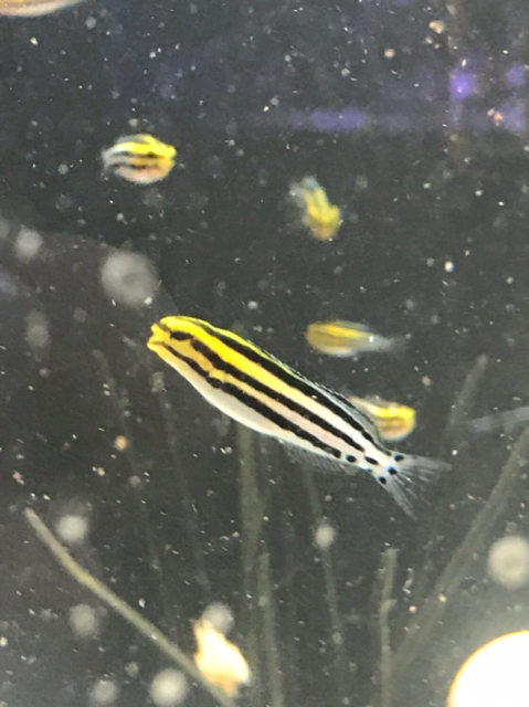
Ok, well I will get to that today. I will do that as soon as i can as well as wire up the next test as well. I had to take a break for awhile. I read a little about motion as you were telling me to install earlier. Doesn’t look like I’m ready for all that at the moment so I will move I’ve got a new batch of blennies born last night that I need to start straining out some baby copepods for, and start souping up my rotifers. It will be the biggest hatch I’ve done as of yet in order to hopefully get some nice trade credit at a LFS for some more expensive broodstock.
I have several tanks, most are plumbed central circulation, as is typical broodstock setup. Not only that but I have to have separate tanks or tank systems for each stage, each with differences that need to be monitored. I’m using a whole heap of electrical outlets and looking at the reef pi the be able to automate all my tasks and at same time making it safer and more organized. It’s not a business, just a hobby but it’s the same amount of work. I’m still learning a lot. It’s a lot to keep up with. I’d like to see some sort of database down the road to store test results and set reminders as well. Wanted to share with you guys how cool it is to raise a few fish, just for a break from the tech talk. Some eye candy, lol.
0cde76a58a03e2a00db7878ef3ce875b.jpg
77bd52ea5cf26c31a60f1250bd35cced.jpg
 
Can anyone tell me how to start a reef pi build thread? I’m sure it’s really simple but not sure where to post. Is it in with tank builds?
 
Do they use a 5v signal or 10v, like reef octopus and tunze?
I assume you are asking either Diamond1 or me about the pump controls? On the Current USA Eflux controller I have, I measured the manual speed control knob (potentiometer) signals and it has a 0-5v output to the motor controller IC. I can't speak for the Jebao as I haven't measured that.
 
Ok, well I will get to that today. I will do that as soon as i can as well as wire up the next test as well. I had to take a break for awhile. I read a little about motion as you were telling me to install earlier. Doesn’t look like I’m ready for all that at the moment so I will move I’ve got a new batch of blennies born last night that I need to start straining out some baby copepods for, and start souping up my rotifers. It will be the biggest hatch I’ve done as of yet in order to hopefully get some nice trade credit at a LFS for some more expensive broodstock.
I have several tanks, most are plumbed central circulation, as is typical broodstock setup. Not only that but I have to have separate tanks or tank systems for each stage, each with differences that need to be monitored. I’m using a whole heap of electrical outlets and looking at the reef pi the be able to automate all my tasks and at same time making it safer and more organized. It’s not a business, just a hobby but it’s the same amount of work. I’m still learning a lot. It’s a lot to keep up with. I’d like to see some sort of database down the road to store test results and set reminders as well. Wanted to share with you guys how cool it is to raise a few fish, just for a break from the tech talk. Some eye candy, lol.
0cde76a58a03e2a00db7878ef3ce875b.jpg
77bd52ea5cf26c31a60f1250bd35cced.jpg
Paul, I love reading through your breeding posts. Did the clown pairs started spawning ?
 
Hello Guys,

Having some issues getting the temperature sensor reading with my Pi Zero W. I had "something" working last night. I was reading three different "temperature" sensors with only one sensor plugged in, and none of them seemed accurate (off by over 12 degrees (f)). It also wasn't working out of the box, but I did something (don't remember what) and was finally able to see it.

So I reformatted the sdcard to try again and still not getting anything read. I have i2c & w1 gpio enabled through the raspi-config. Running the latest 2.0 rc3

My boot.txt looks like:
Code:
pi@reefpi:~ $ cat /boot/config.txt
# For more options and information see
# http://rpf.io/configtxt
# Some settings may impact device functionality. See link above for details

# uncomment if you get no picture on HDMI for a default "safe" mode
#hdmi_safe=1

# uncomment this if your display has a black border of unused pixels visible
# and your display can output without overscan
#disable_overscan=1

# uncomment the following to adjust overscan. Use positive numbers if console
# goes off screen, and negative if there is too much border
#overscan_left=16
#overscan_right=16
#overscan_top=16
#overscan_bottom=16

# uncomment to force a console size. By default it will be display's size minus
# overscan.
#framebuffer_width=1280
#framebuffer_height=720

# uncomment if hdmi display is not detected and composite is being output
#hdmi_force_hotplug=1

# uncomment to force a specific HDMI mode (this will force VGA)
#hdmi_group=1
#hdmi_mode=1

# uncomment to force a HDMI mode rather than DVI. This can make audio work in
# DMT (computer monitor) modes
#hdmi_drive=2

# uncomment to increase signal to HDMI, if you have interference, blanking, or
# no display
#config_hdmi_boost=4

# uncomment for composite PAL
#sdtv_mode=2

#uncomment to overclock the arm. 700 MHz is the default.
#arm_freq=800

# Uncomment some or all of these to enable the optional hardware interfaces
dtparam=i2c_arm=on
#dtparam=i2s=on
dtparam=spi=off

# Uncomment this to enable the lirc-rpi module
#dtoverlay=lirc-rpi

# Additional overlays and parameters are documented /boot/overlays/README

# Enable audio (loads snd_bcm2835)
dtparam=audio=on

#ReefPi Settings
dtparam=i2c_arm=on
dtoverlay=w1-gpio
dtoverlay=pwm-2chan

(I tried specifying the gpio pin also, but it didn't make a difference).

lsmod:
Code:
pi@reefpi:~ $ sudo lsmod
Module                  Size  Used by
bnep                   11981  2
hci_uart               27218  1
btbcm                   8248  1 hci_uart
serdev                  9370  1 hci_uart
bluetooth             366986  24 hci_uart,bnep,btbcm
ecdh_generic           17649  1 bluetooth
brcmfmac              273230  0
brcmutil                9114  1 brcmfmac
snd_bcm2835            23253  0
snd_pcm                89686  1 snd_bcm2835
snd_timer              22428  1 snd_pcm
cfg80211              542402  1 brcmfmac
snd                    60154  3 snd_timer,snd_bcm2835,snd_pcm
rfkill                 21476  6 bluetooth,cfg80211
i2c_bcm2835             6465  1
pwm_bcm2835             3254  0
w1_gpio                 4566  0
wire                   31600  1 w1_gpio
cn                      5687  1 wire
hwmon                  10505  1 wire
uio_pdrv_genirq         3718  0
uio                     9901  1 uio_pdrv_genirq
fixed                   3033  0
i2c_dev                 6674  2
ip_tables              12427  0
x_tables               22130  1 ip_tables
ipv6                  397455  24

Was expecting to see something like:
wire 31600 2 w1_gpio,w1_therm

But that won't show without doing a sudo modprobe w1-therm

Based on the /sys/bus/w1/devices it doesn't appear to be seeing the sensor.

Pic of the breadboard attached.

Any thoughts or something stupid I am overlooking?

IMG_20181118_133813.jpg


Edit: Oh yeah, I get this error:

Nov 18 13:11:45
Failed to initialize i2c. Error:open /dev/i2c-1: no such file or directory


When I was able to get rid of that error ( messing with the i2c settings in the config based with what I found online) that's when the "three" temp sensors appeared...
 
Last edited:
Can I ask, I have mars aqua leds 165w x4 all stripped down so modding them I'm not worried about, but if I want to pwm them properly how could I do it? The panels themselves contain 55 3w leds, I have 4 panels, so a total led count of 220 3w leds.

Now there split into 2 channels per panel, white and blue channel, blue channel uses 27 leds 3w each, white channel 28 leds 3w each, it uses 8 drivers that have manual dimming.

Now I'm thinking to replace how there powered by a better system than supplied so they can then be fully controlled by reef-pi via pwm and timers from the pi.

I've been researching some but it's very confusing on the power side of things, has anyone done anything like this? Or any advice about powering a strip of 108 blue 3w leds and pwm and a strip of 112 mixed white channel leds 3w.

Is it even possible to power and pwm so many leds in series?
 

TOP 10 Trending Threads

ARE YOU READY TO CONFESS TO CRAZIEST, DUMBEST, FUNNIEST THING YOU’VE EVER DONE IN REEFING?

  • Yeah, I'll confess! (Share your story in the comments!)

    Votes: 33 54.1%
  • Nah, I'll keep mine a secret...(Don't be like that, share with the class!)

    Votes: 28 45.9%
Back
Top
Home
Post thread…
Market
What's new