- Joined
- Oct 3, 2019
- Messages
- 679
- Reaction score
- 694
Some of my previous repairs:
 www.reef2reef.com
www.reef2reef.com
www.reef2reef.com
www.reef2reef.com
www.reef2reef.com
FixReef is now also on YouTube!
https://www.youtube.com/channel/UCMAmpCr_0gSwhmTNGzXTPtg
Enjoy this repair, now in HD")
Ahh... at last, no more Apex repairs. All EB832 12v power supplies upgraded, all AquaBus ports fixed. It's time to relax and take a break.
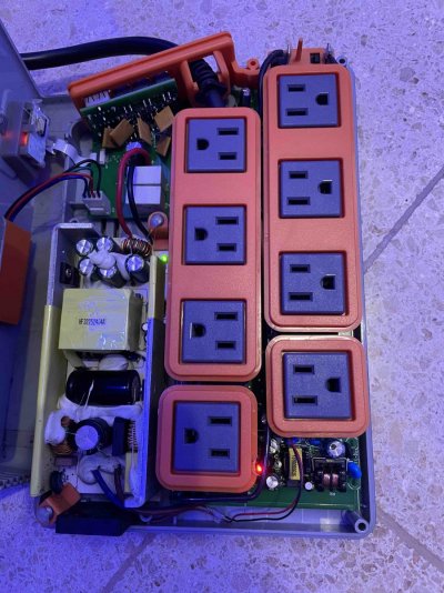
This was the day I received this EB832 in for repair from a fellow reefer:

The reported issue is that it causes the head unit to reboot constantly, but only if the head unit is no longer powered by it's own, dedicated power supply.
By now we all know that the power to the head unit, or any other passive Apex module, is being provided by an EB832 via the 12v AquaBus port.
I previously discussed a very common issue with the EB832 12v power supply here. Also, there is now a repair video on this subject:
But this case is going to be very different.
The head unit randomly reboots because there is not enough power over the AquaBus port.
But the AquaBus 12v power is not provided by the 12v power supply. And it's a good thing, because that tiny 12v PSU can't even make it past the 1 year warranty period powering the relays.
Instead, the AquaBus power is provided by the larger 24v power supply in the lower right corner of the EB832 unit. So, how do we get 12v on the AquaBus from a 24v power supply? This is where the plot thickens.
If we look on the back of the EB832 main board, we find this peculiar component:

Let's look at it under the microscope:

You are looking at a typical "buck converter". In this specific configuration it is responsible for converting 24v into 12v by generating 24v pulses at a specific frequency. Then the pulses gets smoothed out by the inductor (mounted on the other side of the board) and capacitors and on the output we get a clean 12v power. Resistors R50 and R21 set the output voltage of this buck converter circuit.
This buck converter generates 12v output to power any and all passive devices connected to this EB832 over any of it's AquaBus ports.
It is not easy to see on the picture, but the area of the board around the buck converter circuit is significantly discolored. Which is consistent with excessive temperature stress.
But testing the output of this buck converter shows that it's capable of generating 12v output as it should. So why would it cause the head unit to reboot randomly? Let's find out!
If the voltage on the AquaBus port is reasonably constant at ~12v, then the only plausible explanation is that the load current on the port exceeds the capacity. If your return pump can deliver 2400gph, but it's connected over a 1/2" 12ft pipe, you won't be able to maintain the flow.
According to the datasheet, this buck converter can deliver up to 1.5A current under the ideal conditions. So despite the fact that the 24v PSU is reportedly 90w (3.95A @24v), the maximum it can produce across all AquaBus ports is less than 1.5A.

I will say that in all of my testing, these buck converters fail at around 650mA load. But what does this mean for our specific case of the head unit reboot? Let's first find out how much current is being consumed by the head unit and the display, which is probably the most basic configuration.

Looks like the classic head unit and the display I had on my workbench consume about 185mA. Which is about a third of the total capacity of the EB832 12v circuit.
The higher the load on the buck converter, the higher it's temperature.

Referencing the datasheet again, this specific model of the buck converter can operate at the maximum junction temperature of 150C and the ambient temperature of 85C. Those are not necessarily bad numbers, but let's measure what we get in reality.
I will begin this test with a known good EB832 and will attach a temperature probe directly to the buck converter chip. Then I apply a 400mA load on the AquaBus port and measure the temperature of the buck converter while making sure it can provide the power over an extended period of time:

In the known good configuration, the buck converter heats up to 68C (~155F) while providing stable 12v output at 400mA load.
The failing EB832 also got the buck converter to almost 69C, but once it reached that temperature, it immediately failed to produce the required power under the same load:

The buck converter is busted. I can't help it, so here comes another rant:
[RANT]
Neptune sell dozens of Apex modules. Most of them are passive and rely on the AquaBus port to be powered. EB832 is essentially the primary power supply for the entire Apex ecosystem. It is expected to power it all if and when necessary. By design, we are allowed to daisy-chain many modules together. Potentially creating a significant load on the AquaBus power. For this, each module has two AquaBus ports.
EB832 was even conceived with this requirement in mind. This is why it has a 90W, 24V power supply, which is plenty big. So why is it that the power output is then further restricted by a small buck converter circuit which can barely provide 6W power to be shared across all passive modules, including the head unit??? The circuit which is know to have stability issue due to overheating.
Why couldn't there be a dedicated, high quality and capacity, 12v power supply for just the purpose of providing AquaBus power?
If the buck converter circuit was chosen, why the buck converter was selected to be the middle of the road quality for something as critical as the power source for the head unit?
If it was designed to run constantly at high loads, why the heat dissipation was not better organized?
[/RANT]
But I digress. Mind you that this failing buck converter is not completely dead. If it were, the entire EB832 would have been mostly dead. The problem is that the 12v output is still being generated. But the moment it reaches the magic temperature, it shuts off due to internal damage caused by excessive heat over an extended period of time.
This is why the area on the board around the buck converter was discolored and the buck converter looked rough. This is also why the head unit would reboot randomly, but then would come back on, after the buck converter gets a chance to cool off and reset.
But enough talking, this EB832 is hurting and it's time to make it happy again.
First, let's remove the failing buck converter:

The area is clean, has some fresh solder added and ready to accept the replacement:

Similar to my other repairs, if I know that there is a common problem, I try not to do the repair by just replacing one low quality component with another equally low quality component.
For this repair, I am going to select a higher quality automotive buck converter chip, especially designed to operate at higher ambient temperatures inside a vehicle. It will still get very hot at higher loads on AquaBus, but it will be able to withstand overheating much better and provide the reliable 12v output.

Now that the new buck converter is installed, let's test the load:

This time I'm applying a higher load of 450mA and the new buck converter does get to the 76C, but it had no issues providing this load over an extended period of testing. This EB832 is happy again and, hopefully, it will also last this reefer much longer than the original.
But the most important takeaway from this tale is that we should not trust the stock EB832 to provide power over AquaBus to more than a few passive components. I recommend avoiding more than 5-6 passive modules including the head unit. Whenever possible, use dedicated power supplies for each individual module, especially the head unit, and watch to make sure it's always plugged in. The total number of passive modules should further be reduced if using very long AquaBus cables, as it will place additional load on the weak 12v circuit.
In the next episode of the repair saga, I will amuse you with yet another peculiar AquaBus power issue related to this buck converter. Stay tuned.
EB832 Attempting to Communicate with Apex (Bootloader Mode)
Some of my previous repairs: https://www.reef2reef.com/threads/radion-xr30-complete-no-light-repair.792711/ https://www.reef2reef.com/threads/radion-xr15-doesnt-power-on-due-to-corrosion-repair.809136/ https://www.reef2reef.com/threads/another-attempt-at-fixing-apex-eb832.804717/ And as always...
Another attempt at fixing Apex EB832
Some of my previous repairs: https://www.reef2reef.com/threads/radion-xr30-complete-no-light-repair.792711/ https://www.reef2reef.com/threads/radion-lights-board-level-repair.774331/ https://www.reef2reef.com/threads/ai-hydra-fan-connector-repair-significant-corrosion.793402/ First off, let me...
Apex Display Module Causes Head Unit to Reboot Repair
Some of my previous repairs: https://www.reef2reef.com/threads/eb832-attempting-to-communicate-with-apex-bootloader-mode.811958/ https://www.reef2reef.com/threads/another-attempt-at-fixing-apex-eb832.804717/...
FixReef is now also on YouTube!
https://www.youtube.com/channel/UCMAmpCr_0gSwhmTNGzXTPtg
Enjoy this repair, now in HD
Ahh... at last, no more Apex repairs. All EB832 12v power supplies upgraded, all AquaBus ports fixed. It's time to relax and take a break.
This was the day I received this EB832 in for repair from a fellow reefer:
The reported issue is that it causes the head unit to reboot constantly, but only if the head unit is no longer powered by it's own, dedicated power supply.
By now we all know that the power to the head unit, or any other passive Apex module, is being provided by an EB832 via the 12v AquaBus port.
I previously discussed a very common issue with the EB832 12v power supply here. Also, there is now a repair video on this subject:
But this case is going to be very different.
The head unit randomly reboots because there is not enough power over the AquaBus port.
But the AquaBus 12v power is not provided by the 12v power supply. And it's a good thing, because that tiny 12v PSU can't even make it past the 1 year warranty period powering the relays.
Instead, the AquaBus power is provided by the larger 24v power supply in the lower right corner of the EB832 unit. So, how do we get 12v on the AquaBus from a 24v power supply? This is where the plot thickens.
If we look on the back of the EB832 main board, we find this peculiar component:
Let's look at it under the microscope:
You are looking at a typical "buck converter". In this specific configuration it is responsible for converting 24v into 12v by generating 24v pulses at a specific frequency. Then the pulses gets smoothed out by the inductor (mounted on the other side of the board) and capacitors and on the output we get a clean 12v power. Resistors R50 and R21 set the output voltage of this buck converter circuit.
This buck converter generates 12v output to power any and all passive devices connected to this EB832 over any of it's AquaBus ports.
It is not easy to see on the picture, but the area of the board around the buck converter circuit is significantly discolored. Which is consistent with excessive temperature stress.
But testing the output of this buck converter shows that it's capable of generating 12v output as it should. So why would it cause the head unit to reboot randomly? Let's find out!
If the voltage on the AquaBus port is reasonably constant at ~12v, then the only plausible explanation is that the load current on the port exceeds the capacity. If your return pump can deliver 2400gph, but it's connected over a 1/2" 12ft pipe, you won't be able to maintain the flow.
According to the datasheet, this buck converter can deliver up to 1.5A current under the ideal conditions. So despite the fact that the 24v PSU is reportedly 90w (3.95A @24v), the maximum it can produce across all AquaBus ports is less than 1.5A.
I will say that in all of my testing, these buck converters fail at around 650mA load. But what does this mean for our specific case of the head unit reboot? Let's first find out how much current is being consumed by the head unit and the display, which is probably the most basic configuration.
Looks like the classic head unit and the display I had on my workbench consume about 185mA. Which is about a third of the total capacity of the EB832 12v circuit.
The higher the load on the buck converter, the higher it's temperature.
Referencing the datasheet again, this specific model of the buck converter can operate at the maximum junction temperature of 150C and the ambient temperature of 85C. Those are not necessarily bad numbers, but let's measure what we get in reality.
I will begin this test with a known good EB832 and will attach a temperature probe directly to the buck converter chip. Then I apply a 400mA load on the AquaBus port and measure the temperature of the buck converter while making sure it can provide the power over an extended period of time:
In the known good configuration, the buck converter heats up to 68C (~155F) while providing stable 12v output at 400mA load.
The failing EB832 also got the buck converter to almost 69C, but once it reached that temperature, it immediately failed to produce the required power under the same load:
The buck converter is busted. I can't help it, so here comes another rant:
[RANT]
Neptune sell dozens of Apex modules. Most of them are passive and rely on the AquaBus port to be powered. EB832 is essentially the primary power supply for the entire Apex ecosystem. It is expected to power it all if and when necessary. By design, we are allowed to daisy-chain many modules together. Potentially creating a significant load on the AquaBus power. For this, each module has two AquaBus ports.
EB832 was even conceived with this requirement in mind. This is why it has a 90W, 24V power supply, which is plenty big. So why is it that the power output is then further restricted by a small buck converter circuit which can barely provide 6W power to be shared across all passive modules, including the head unit??? The circuit which is know to have stability issue due to overheating.
Why couldn't there be a dedicated, high quality and capacity, 12v power supply for just the purpose of providing AquaBus power?
If the buck converter circuit was chosen, why the buck converter was selected to be the middle of the road quality for something as critical as the power source for the head unit?
If it was designed to run constantly at high loads, why the heat dissipation was not better organized?
[/RANT]
But I digress. Mind you that this failing buck converter is not completely dead. If it were, the entire EB832 would have been mostly dead. The problem is that the 12v output is still being generated. But the moment it reaches the magic temperature, it shuts off due to internal damage caused by excessive heat over an extended period of time.
This is why the area on the board around the buck converter was discolored and the buck converter looked rough. This is also why the head unit would reboot randomly, but then would come back on, after the buck converter gets a chance to cool off and reset.
But enough talking, this EB832 is hurting and it's time to make it happy again.
First, let's remove the failing buck converter:
The area is clean, has some fresh solder added and ready to accept the replacement:
Similar to my other repairs, if I know that there is a common problem, I try not to do the repair by just replacing one low quality component with another equally low quality component.
For this repair, I am going to select a higher quality automotive buck converter chip, especially designed to operate at higher ambient temperatures inside a vehicle. It will still get very hot at higher loads on AquaBus, but it will be able to withstand overheating much better and provide the reliable 12v output.
Now that the new buck converter is installed, let's test the load:
This time I'm applying a higher load of 450mA and the new buck converter does get to the 76C, but it had no issues providing this load over an extended period of testing. This EB832 is happy again and, hopefully, it will also last this reefer much longer than the original.
But the most important takeaway from this tale is that we should not trust the stock EB832 to provide power over AquaBus to more than a few passive components. I recommend avoiding more than 5-6 passive modules including the head unit. Whenever possible, use dedicated power supplies for each individual module, especially the head unit, and watch to make sure it's always plugged in. The total number of passive modules should further be reduced if using very long AquaBus cables, as it will place additional load on the weak 12v circuit.
In the next episode of the repair saga, I will amuse you with yet another peculiar AquaBus power issue related to this buck converter. Stay tuned.
Last edited: