Buddy's Reef-Pi Build

buddy.

Active Member
View Badges
Joined
May 16, 2018
Messages
291
Reaction score
617
Location
Australia
Rating - 0%
0   0   0
Hey everyone! Here is another #reef-pi build for anyone interested in following :D
My build will consist of @Ranjib reef-pi (of course) and I will also be using the HAT and PWM module from @wykat .

I only have a laptop so I couldn't do the standard raspberry pi set up with a mouse and keyboard, so I found a guide to set up the SD card with SSH and wifi enabled.
I downloaded Raspbian and flashed it on to the SD card with Etcher.

Once it is flashed you need to create an empty text file on the card called "SSH".

IF you want to use wifi you also need to create a text file called wpa_supplicant.conf with the following lines
ctrl_interface=DIR=/var/run/wpa_supplicant GROUP=netdev
network={
ssid="YOUR NETWORK NAME"
psk="YOUR PASSWORD"
key_mgmt=WPA-PSK
}

Put the card in to the pi and power it on. Now you need to find the IP address of the pi. I used a program called nmap.
To do this, open the command prompt and enter nmap -sn YOUR IP ADDRESS/24
It will take a few seconds and then list everything on your network.

Next is to SSH in to the pi by entering ssh pi@PI IP ADDRESS
The default login is pi and password is raspberry

From this point you can configure and install everything from the reef-pi guides.
 
Last edited:
OP
OP
buddy.

buddy.

Active Member
View Badges
Joined
May 16, 2018
Messages
291
Reaction score
617
Location
Australia
Rating - 0%
0   0   0
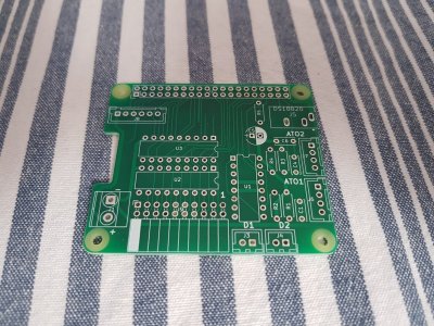
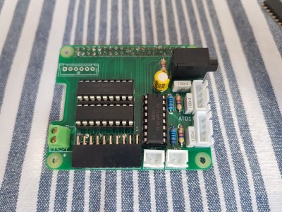
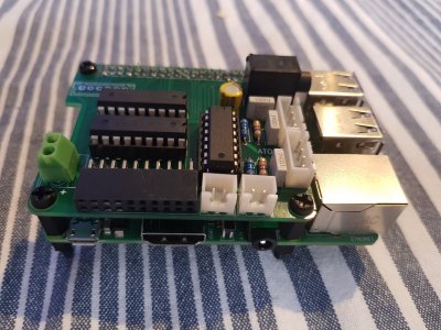
This is the reef-pi HAT stacked on top the raspberry pi. I will also build the PWM board once it is ready.
You can find everything you need to build this here
I used PCBWAY for the board and sourced all of the components from Mouser and Amazon.

20181202_133610.jpg
20181202_145729.jpg
20181202_154223.jpg
 
Last edited:
OP
OP
buddy.

buddy.

Active Member
View Badges
Joined
May 16, 2018
Messages
291
Reaction score
617
Location
Australia
Rating - 0%
0   0   0
I did all the testing on the Adafruit guide while the HAT was disconnected and it all worked well. I also set up email alerts which also worked without any problem.

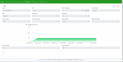
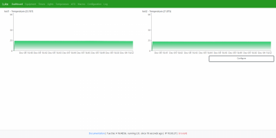
The first issue I am having is with my temperature sensors. I might need help from @Ranjib or @wykat for this. If I connect up the probe directly to the raspberry pi like this, it works perfectly.
sensors_Screen_Shot_2018-09-22_at_5.35.24_PM.png
temp.PNG

But when I use the pi-HAT, the sensor is not getting detected. Where the probe wires connect to the male audio jack I am getting 3.3v on the data and power wires. So the probe is being powered but for some reason its not getting detected.
 

speedstar

Well-Known Member
View Badges
Joined
Sep 18, 2018
Messages
704
Reaction score
1,030
Location
Grand Rapids
Rating - 0%
0   0   0
I did all the testing on the Adafruit guide while the HAT was disconnected and it all worked well. I also set up email alerts which also worked without any problem.

The first issue I am having is with my temperature sensors. I might need help from @Ranjib or @wykat for this. If I connect up the probe directly to the raspberry pi like this, it works perfectly.
sensors_Screen_Shot_2018-09-22_at_5.35.24_PM.png
temp.PNG

But when I use the pi-HAT, the sensor is not getting detected. Where the probe wires connect to the male audio jack I am getting 3.3v on the data and power wires. So the probe is being powered but for some reason its not getting detected.

Are you using the updated documentation that swapped the tip and ring? v1.1
 
OP
OP
buddy.

buddy.

Active Member
View Badges
Joined
May 16, 2018
Messages
291
Reaction score
617
Location
Australia
Rating - 0%
0   0   0
Are you using the updated documentation that swapped the tip and ring? v1.1
I am not sure, could you show me this doc?

Also you may want to swap the 40 pin connector to one with long leads if you ever want to stack another board on there for pwm. https://www.amazon.com/gp/product/B071FT161B/ref=od_aui_detailpages00?ie=UTF8&psc=1
The PWM board doesn't stack on that connector. There is a 6 pin connector that goes next to that 40 pin connector on the top side that I haven't soldered to the board yet as I am not sure if I am going to stack it or not.
 

speedstar

Well-Known Member
View Badges
Joined
Sep 18, 2018
Messages
704
Reaction score
1,030
Location
Grand Rapids
Rating - 0%
0   0   0
I am not sure, could you show me this doc?


The PWM board doesn't stack on that connector. There is a 6 pin connector that goes next to that 40 pin connector on the top side that I haven't soldered to the board yet as I am not sure if I am going to stack it or not.

You right guess i can snip the pins. totally forgot

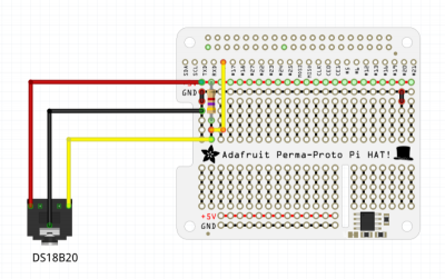
The doc is right in the link you referenced. There was a change from 1.0 to 1.1 as I had the problem you had, and found it was backward when I traced the board. see picture

g.JPG
 

Ranjib

7500 Club Member
View Badges
Joined
Apr 16, 2016
Messages
9,843
Reaction score
17,056
Location
Pleasant Hill, Concord
Rating - 0%
0   0   0
I did all the testing on the Adafruit guide while the HAT was disconnected and it all worked well. I also set up email alerts which also worked without any problem.

The first issue I am having is with my temperature sensors. I might need help from @Ranjib or @wykat for this. If I connect up the probe directly to the raspberry pi like this, it works perfectly.
sensors_Screen_Shot_2018-09-22_at_5.35.24_PM.png
temp.PNG

But when I use the pi-HAT, the sensor is not getting detected. Where the probe wires connect to the male audio jack I am getting 3.3v on the data and power wires. So the probe is being powered but for some reason its not getting detected.
The data wire should not read 3.3v. Can tiunpower down and check for continuity ?
 
OP
OP
buddy.

buddy.

Active Member
View Badges
Joined
May 16, 2018
Messages
291
Reaction score
617
Location
Australia
Rating - 0%
0   0   0
Ok, next problem!
I am testing out my 8 channel 5v relay boards.

First I tested with just the raspberry pi by connecting up the 5v, ground and an outlet GPIO and it worked as expected.

Next I tried with the pi-HAT but it is not activating the relay. The input of the ULN2803 is receiving 3.25v. The ULN2803 is outputting only 0.6v to the relay board.
I tried a different GPIO on the second ULN2803 on the pi-HAT with the exact same result.

The VCC light is on when I connect the relay board to the 5v and GND on the 10pin connector on the pi-HAT.

The ULN inputs have continuity with the GPIO outlets. The ULN outlets also have continuity with the 10pin connector.
The ULN's are also grounded on their number 9 pin and have 5v on their number 10 pin. Measuring the voltage on pin 9 and 10 gives 5v.

Can anyone help me figure out why the ULN2803 output is so low and not activating the relay?
 
Last edited:

wykat

Active Member
View Badges
Joined
May 23, 2018
Messages
182
Reaction score
421
Rating - 0%
0   0   0
You right guess i can snip the pins. totally forgot

The doc is right in the link you referenced. There was a change from 1.0 to 1.1 as I had the problem you had, and found it was backward when I traced the board. see picture

g.JPG
Thanks for attachment, will have to remove the old version :D

@buddy. We can continue here on the relays not working. Unfortunately I don't have your relay board but we should be able to sort this out.
 
OP
OP
buddy.

buddy.

Active Member
View Badges
Joined
May 16, 2018
Messages
291
Reaction score
617
Location
Australia
Rating - 0%
0   0   0
Don't have your relay board, but will try to help.

Yes all components on the picture look ok (direction) and yes, no 12V is required for the relay output.


This is good to know. In order to replicate, can you share which GPIO port you used? What were the values of the GPIO port switching ON/OFF?


In order for me to replicate (without relay board), can you share which pins (relay ports) you measured? Is the behavior the same with and without relay board? (Power consumption?)

Hi @wykat
I will test one outlet on each row of the connector. I have highlighted the differing values in red when comparing the relay board to connected or disconnected.
Do you want me to also run these same tests with the outlet reversed?

Top row: Relay Board Connected
Connector HAT 7, Relays 6, GPIO10.
-ve probe on ground, +ve probe on GPIO - Voltage on the 40 pin connector when on - 3.25v, Voltage on the 40 pin connector when off - 0v
-ve probe on ground, +ve probe on ULN output - Voltage on the 10 pin connector when on - 0.6v, Voltage on the 10 pin connector when off - 0v

-ve probe on ULN output, +ve probe on 5v - Voltage on the 10 pin connector when on - 4.34v, Voltage on the 10 pin connector when off - 4.93v

Top row: Relay Board Disconnected

Connector HAT 7, Relays 6, GPIO10.
-ve probe on ground, +ve probe on GPIO - Voltage on the 40 pin connector when on - 3.25v, Voltage on the 40 pin connector when off - 0v
-ve probe on ground, +ve probe on ULN output - Voltage on the 10 pin connector when on - 0.6v, Voltage on the 10 pin connector when off - 1.2v
-ve probe on ULN output, +ve probe on 5v - Voltage on the 10 pin connector when on - 4.34v, Voltage on the 10 pin connector when off - 1.15v

Bottom row: Relay Board Connected
Connector HAT 14, Relays 3, GPIO22.

-ve probe on ground, +ve probe on GPIO - Voltage on the 40 pin connector when on - 3.25v, Voltage on the 40 pin connector when off - 0v
-ve probe on ground, +ve probe on ULN output - Voltage on the 10 pin connector when on - 0.6v, Voltage on the 10 pin connector when off - 0v
-ve probe on ULN output, +ve probe on 5v - Voltage on the 10 pin connector when on - 4.36v, Voltage on the 10 pin connector when off - 4.93v

Bottom row: Relay Board Disconnected
Connector HAT 14, Relays 3, GPIO22.

-ve probe on ground, +ve probe on GPIO - Voltage on the 40 pin connector when on - 3.25v, Voltage on the 40 pin connector when off - 0v
-ve probe on ground, +ve probe on ULN output - Voltage on the 10 pin connector when on - 0.6v, Voltage on the 10 pin connector when off - 1.3v
-ve probe on ULN output, +ve probe on 5v - Voltage on the 10 pin connector when on - 4.36v, Voltage on the 10 pin connector when off - 1.04v

If I understand correctly, wiring between GPIO/ULN/10 pin connector and power to the ULN chips are all ok. Just to be sure (don't measure voltage, measure ohm), is there a connection between pin 6 of the I2C interface on the Reef-PI_HAT and GND (pin 39 on GPIO)? This has been a failure in the initial design but should be ok on your board. [Edit]should be ok as you're measuring +5V on the ULN power pins[/Edit]
No I am not getting any connection here.

Not sure if it is relevant, but if I have pin 1 and 10 on the 10pin connector connected to GND and VCC on the relay board and then I connect the relay channel directly to the 5v or the 3.3 on the pi then the relay works.
I hope this helps!!
 
Last edited:

wykat

Active Member
View Badges
Joined
May 23, 2018
Messages
182
Reaction score
421
Rating - 0%
0   0   0
Hi @wykat
I will test one outlet on each row of the connector. I have highlighted the differing values in red when comparing the relay board to connected or disconnected.
Do you want me to also run these same tests with the outlet reversed?

Top row: Relay Board Connected
Connector HAT 7, Relays 6, GPIO10.
-ve probe on ground, +ve probe on GPIO - Voltage on the 40 pin connector when on - 3.25v, Voltage on the 40 pin connector when off - 0v
-ve probe on ground, +ve probe on ULN output - Voltage on the 10 pin connector when on - 0.6v, Voltage on the 10 pin connector when off - 0v

-ve probe on ULN output, +ve probe on 5v - Voltage on the 10 pin connector when on - 4.34v, Voltage on the 10 pin connector when off - 4.93v

Top row: Relay Board Disconnected

Connector HAT 7, Relays 6, GPIO10.
-ve probe on ground, +ve probe on GPIO - Voltage on the 40 pin connector when on - 3.25v, Voltage on the 40 pin connector when off - 0v
-ve probe on ground, +ve probe on ULN output - Voltage on the 10 pin connector when on - 0.6v, Voltage on the 10 pin connector when off - 1.2v
-ve probe on ULN output, +ve probe on 5v - Voltage on the 10 pin connector when on - 4.34v, Voltage on the 10 pin connector when off - 1.15v

Bottom row: Relay Board Connected
Connector HAT 14, Relays 3, GPIO22.

-ve probe on ground, +ve probe on GPIO - Voltage on the 40 pin connector when on - 3.25v, Voltage on the 40 pin connector when off - 0v
-ve probe on ground, +ve probe on ULN output - Voltage on the 10 pin connector when on - 0.6v, Voltage on the 10 pin connector when off - 0v
-ve probe on ULN output, +ve probe on 5v - Voltage on the 10 pin connector when on - 4.36v, Voltage on the 10 pin connector when off - 4.93v

Bottom row: Relay Board Disconnected
Connector HAT 14, Relays 3, GPIO22.

-ve probe on ground, +ve probe on GPIO - Voltage on the 40 pin connector when on - 3.25v, Voltage on the 40 pin connector when off - 0v
-ve probe on ground, +ve probe on ULN output - Voltage on the 10 pin connector when on - 0.6v, Voltage on the 10 pin connector when off - 1.3v
-ve probe on ULN output, +ve probe on 5v - Voltage on the 10 pin connector when on - 4.36v, Voltage on the 10 pin connector when off - 1.04v


No I am not getting any connection here.

Not sure if it is relevant, but if I have pin 1 and 10 on the 10pin connector connected to GND and VCC on the relay board and then I connect the relay channel directly to the 5v or the 3.3 on the pi then the relay works.
I hope this helps!!
Sorry for delay, but have some problems in debugging since my old Reef-PI software doesn't start without PWM module and with the PWM module attached I don't have access to measure voltages on the HAT components. Nevertheless my relays do work with the new HAT module (with PWM attached as well), so I can verify your observations after I've upgraded to the latest Reef-PI software (that version should also start when no PWM module is attached).

It's strange that you have no connection between pin 6 of the I2C bus and GND? Just to be sure, the latest HAT board has thick connections at the bottom side under the L293D going to the motor connectors with almost no space for additional connections. The old board hat just some thin connections, that's how I recognize the difference between the 2 boards. (will need to update the silk screen on Github, my PCB's show 'Reef-PI HAT v1.0')

Your last statement is interesting and since you're using sockets for the ULN2803 chips, can you remove both U2 & U3 chips and make a direct connection between pins U2-6 and U2-13 (for HAT 7, Relays 6, GPIO10). Then it's the same as connecting the relays directly to GPIO10, the ULN2803 is basically just a protection for the GPIO ports. If that works then your relay board doesn't like the ULN2803 for some reason.
 
Last edited:
OP
OP
buddy.

buddy.

Active Member
View Badges
Joined
May 16, 2018
Messages
291
Reaction score
617
Location
Australia
Rating - 0%
0   0   0
Sorry for delay, but have some problems in debugging since my old Reef-PI software doesn't start without PWM module and with the PWM module attached I don't have access to measure voltages on the HAT components. Nevertheless my relays do work with the new HAT module (with PWM attached as well), so I can verify your observations after I've upgraded to the latest Reef-PI software (that version should also start when no PWM module is attached).

It's strange that you have no connection between pin 6 of the I2C bus and GND? Just to be sure, the latest HAT board has thick connections at the bottom side under the L293D going to the motor connectors with almost no space for additional connections. The old board hat just some thin connections, that's how I recognize the difference between the 2 boards. (will need to update the silk screen on Github, my PCB's show 'Reef-PI HAT v1.0')

Your last statement is interesting and since you're using sockets for the ULN2803 chips, can you remove both U2 & U3 chips and make a direct connection between pins U2-6 and U2-13 (for HAT 7, Relays 6, GPIO10). Then it's the same as connecting the relays directly to GPIO10, the ULN2803 is basically just a protection for the GPIO ports. If that works then your relay board doesn't like the ULN2803 for some reason.

Sorry I misunderstood which connection you wanted me to check on the I2C, I can definitely confirm that I have a connection to ground on pin6.
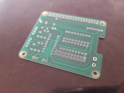
I have uploaded a picture of one of my spare boards just to confirm this with you.
20181206_062322.jpg

I removed the ULN chips and put a jumper wire in the sockets as you described.
The relay does work in normal and reversed mode!
After this, I tried a brand new ULN chip but then the relay does not work again. You must be right in saying that my relay board does not like the ULN chips.

Do you think there is an alternative solution to getting the chips working with the board or will I need to buy different boards?
 
Back
Top