Flow Sensors - Usage and Example setup

Users Who Are Viewing This Thread (Total: 1, Members: 0, Guests: 1)

EdsReefOdyssey

Active Member
View Badges
Joined
Oct 29, 2017
Messages
153
Reaction score
79
Rating - 0%
0   0   0
Thanks! That was actually my question [emoji1]... I have 25mm pipe. So which sensor will provide the min restriction? The 9000l/h or the 6000L/h?

Understand that Marco kind of stole my thunder with the announcement but could anyone let me know what is the correct (metric) flow sensor for 25mm pipe [emoji16]?

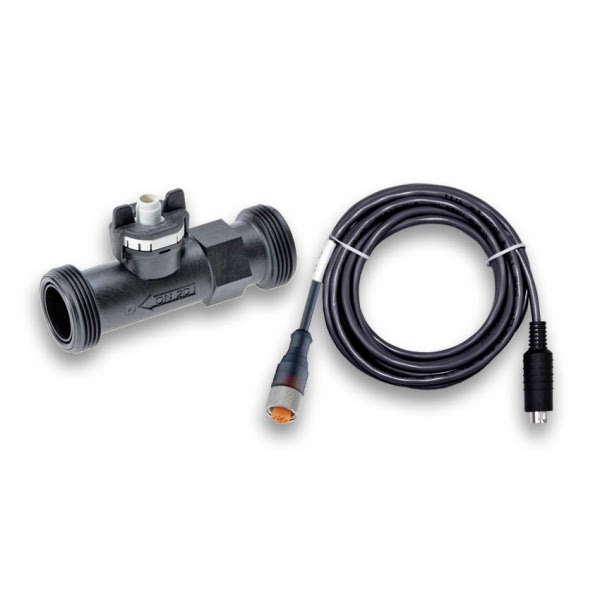
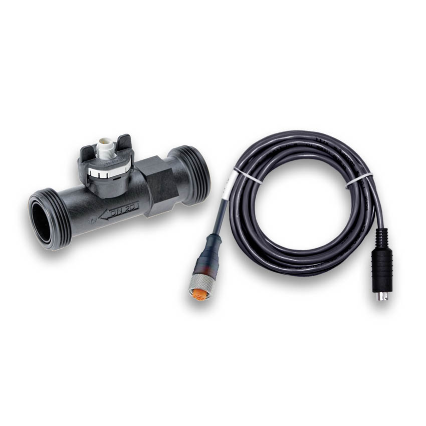
Heres a little more info about the GHL vortex flow sensors. Hope it helps.
Flow Sensor 2000 l/h - 10mm (3/8″ ID) (26gph – 528gph)
Flow Sensor 5000 l/h - 20mm (3/4″ ID) (79gph – 1,320gph)
Flow Sensor 9000 l/h - 25mm (1″ ID) (142gph – 2,377gph)
 

csund

Active Member
View Badges
Joined
Dec 23, 2013
Messages
250
Reaction score
252
Location
Seattle
Rating - 0%
0   0   0
Are you able to calculate the gph of two flow sensors to control one pump?

My return splits from 1” into two 3/4”. With the union adapters the 9000 lph flow sensor is 3/4” so I would need two after the split.
 

EdsReefOdyssey

Active Member
View Badges
Joined
Oct 29, 2017
Messages
153
Reaction score
79
Rating - 0%
0   0   0
Is everyone subscribed to our news letter? Because there was one sent out 2 days ago that had some good news regarding flow sensors...

New products: Coming soon
f3I2xzn1Ru-aE9ziQuBouE-4G_q9QZS3w_YZzA4of27urZCoFMeMmMFuuzyJCf2t_woVHgNiJdJgurMMY-ogTsuedUb3PAqMEplagAn8HMpTlYwPglOhVvfq6HG5PKK-Uf8JDk_uWYkoeMVOyaqTxx1_e2JNpjxaX5w=s0-d-e1-ft

Flow sensor IMPERIAL fittings
Imperial socket fitting for Flow Sensor 5000 / 9000 models; pack of 2
PL-1667 / PL-1668, respectively

Flow sensor METRIC fittings
Metric socket fitting for Flow Sensor 2000 / 5000 / 9000 models; pack of 2
PL-1664 / PL-1665 / PL-1666, respectively

https://www.aquariumcomputer.com/usa/product/pvc-fittings-imperial-for-flow-sensor-9000l-h/

Why 3/4" and not 1"? :confused:
 

Ashir Parekh

Community Member
View Badges
Joined
May 29, 2018
Messages
85
Reaction score
170
Location
South Africa
Rating - 0%
0   0   0
Question regarding flow meters. I have 2 pumps. Both plumbed with 32mm pipe. Main return pump is a Varios 8. It will go straight up and split into 2 returns. Can i add the 9000lph flow meter vertically and if so can i use reducers from 32mm to 25mm then back to 32mm. Will this affect the readings in any way? Second pump runs into a manifold which then feeds chiller, algae reactor, gfo and carbon reactor. Is it worth putting a flow meter before the manifold itself. This manifold is run by a varios 6. Thanks all
 

Ditto

Valuable Member
View Badges
Joined
Apr 25, 2017
Messages
2,229
Reaction score
2,972
Location
Albany, NY
Rating - 0%
0   0   0
As long as you provide a few inches for the reduction on either side it should be ok. I had to use a reducer on my one table to go from 1.5” to 1” back go 1.5” I did 3 inches on each side as a safety net for turbulence.

I placed the flow meter also on the manifolds feed only to get an idea of how much water I was pushing into my manifold. It allowed me to get an idea of the overall flow in and then adjust the overall speed of the pump.
 

Ashir Parekh

Community Member
View Badges
Joined
May 29, 2018
Messages
85
Reaction score
170
Location
South Africa
Rating - 0%
0   0   0
As long as you provide a few inches for the reduction on either side it should be ok. I had to use a reducer on my one table to go from 1.5” to 1” back go 1.5” I did 3 inches on each side as a safety net for turbulence.

I placed the flow meter also on the manifolds feed only to get an idea of how much water I was pushing into my manifold. It allowed me to get an idea of the overall flow in and then adjust the overall speed of the pump.

Thanks for this @Ditto , So the reducer must be at least 3 or more inches away from the flow meter. Can do that and as for having the flow meter positioned vertically shouldn't be an issue i assume.
 

Ditto

Valuable Member
View Badges
Joined
Apr 25, 2017
Messages
2,229
Reaction score
2,972
Location
Albany, NY
Rating - 0%
0   0   0
Not at all you can for sure put it vertical. On my one tank that has the sump in the basement it is on the return line off the pump in the basement vertical about 3 feet after the pump.
 
Last edited:

Enea

New Member
View Badges
Joined
May 8, 2019
Messages
15
Reaction score
36
Rating - 0%
0   0   0
@Ditto but doesn't the reduction from from 1.5 "to 1" back go 1.5 "cause a decrease in flow rate?

The fact that there is a reduction should not distort the result of the flow meter? in theroy, speed and pressure change in the bottleneck?
 

Ditto

Valuable Member
View Badges
Joined
Apr 25, 2017
Messages
2,229
Reaction score
2,972
Location
Albany, NY
Rating - 0%
0   0   0
Yes, I do loose some flow. How much not really sure. But with a return pump being a red dragon speedy 3 rated I would just turn it up .5 of a volt to compensate for the loss.
 

Enea

New Member
View Badges
Joined
May 8, 2019
Messages
15
Reaction score
36
Rating - 0%
0   0   0
@Ditto

I have a red dragon 3 hight pression 9000.

I start with a 32 mm tube and then divide it into two 25 mm tubes with a Y. I
n a 25 mm line I installed the 25 mm flow meter.

the flow meter is set in a 50% bypass system so it gives me the correct reading of my flow.

I tried to set the red dragon through 1-10V in constant flow mode. But the pump cannot keep up as it turns off when too much flow passes and turns on at maximum when too little passes. In this way the overflow fills up and becomes unstable.


then I set it via streampump. But even this mode, when the 20% of power in the software is actually set, the pump in reality is the pump at 46%
 

Ashir Parekh

Community Member
View Badges
Joined
May 29, 2018
Messages
85
Reaction score
170
Location
South Africa
Rating - 0%
0   0   0
@Ditto

I have a red dragon 3 hight pression 9000.

I start with a 32 mm tube and then divide it into two 25 mm tubes with a Y. I
n a 25 mm line I installed the 25 mm flow meter.

the flow meter is set in a 50% bypass system so it gives me the correct reading of my flow.

I tried to set the red dragon through 1-10V in constant flow mode. But the pump cannot keep up as it turns off when too much flow passes and turns on at maximum when too little passes. In this way the overflow fills up and becomes unstable.


then I set it via streampump. But even this mode, when the 20% of power in the software is actually set, the pump in reality is the pump at 46%

So i was just chatting to my good friend who is in the water business. He will be doibg my plumbing.

According to him if i run a 32mm pipe then down to 25mm then back to 32mm, i am automatically using only 25mm. So no point going back to 32mm. 1 option is to just run 25mm pipe to my returns. Varios 8 is about 10000 lph. Will 25mm handle this type of water volume, also be aware that i will be splitting my return into 2 return lines.

2nd option is to split into 2 Like ditto but still keeping 25mm at the end. Which is best.

Pictures for reference.

6AECC7BF-27E4-4E20-A914-EEB98928DEFC.jpeg


8FAAEBD5-8BE9-4083-9A95-6FE7CE1855F2.jpeg
 

Enea

New Member
View Badges
Joined
May 8, 2019
Messages
15
Reaction score
36
Rating - 0%
0   0   0
@Ditto yesterday I tried to adjust the L1(0-10V) port and I discovered that at 6.4 V the pump Red Dragon 9.0 higpresur is already at maximum wat. Now I have set 0-6.4V and in the stream pump and the measurement corresponds approximately to the wat on the pump controller.

however if I put the costant flow mode, the pump starts to destabilize. I set 2500l / h as a nominal value.
the first pump goes to 4000l / h then turns off, when it falls below 2500l / h it turns on, only that the increase of the L1 port is too fast that passes from 0V to 6.4V to return the flow to the correct value and then passing the 2500l / h it goes off again.

to solve the problem, i need to find a way to insert a pause between one increment and another in order to give the flow meter time to read the right value based on the power of the pump.
 

AZMSGT

2500 Club Member
View Badges
Joined
May 6, 2019
Messages
3,988
Reaction score
7,896
Rating - 0%
0   0   0
Hi All, sorry just shaking this thread back to life. @Vinny@GHLUSA
Does the internal diameter of flow sensor have to match your plumbing internal diameter to monitor accurate flow?
Are the probes "calibrated" (or perhaps the P4 programmed) to know the diameter of the piece of tube they are in to allow the liters per hour calculation to be made?

I’m going to say no. The reason is that for instance the 9000lph sensor inside diameter is 32mm however the union fittings that go on it reduce things to 25mm. The other flow sensors fittings reduce flow similarly.
The flow reduction does create turbulent water flow past the sensors. I know my sensors are always showing the flow fluctuating.
 

Be102

Valuable Member
View Badges
Joined
Nov 29, 2016
Messages
1,884
Reaction score
1,059
Rating - 0%
0   0   0
I’d like to add a flow sensor from my return to my display and was wondering if someone could help guide me into the size connections I need

my return line 11/4 standard pvc

I also would potentially like to add a flow sensor off of my return that connects to my manifold

my manifold t’s off the return @ 3/4’

what would I need for plumbing supplies to connect?
I’ll attach picture of setup

2C4F6FE4-7DE4-4F3A-9C04-1C0001AB8375.jpeg A7A2FA5D-6D58-46AD-80BF-58E70EADB874.jpeg
 

Member No 1

Well-Known Member
View Badges
Joined
Dec 17, 2017
Messages
625
Reaction score
430
Location
Rehoboth, MA
Rating - 0%
0   0   0
Let's talk flow sensors. How could a flow sensor be a useful addition to your system, what can you do with it, and how to configure it.

FlowSensorWithCable850x850.jpg


  • Basic usage: Monitor flow rate(s), return pump, media reactors, UV, refugium, skimmer etc..
  • Advanced usage: Monitor and Control Flow to parts of the system, in combination with 0-10v Controllable pumps.


On my system, I use it to keep a pre-set and steady amount of flow to the display from my return pump.
Why not just set the pump and forget it? Because manifold and media reactors.

I run a single return pump(Royal Exclusiv RD3 80w 10v controllable) with a manifold feeding 2x media reactors with Carbon and Phosphate Remover.

Occasionally the reactors require media change-out, or flow adjustment depending on the media, fill level, etc.
With the flow sensor configured, I can open up both reactors, or shut them off completely, within seconds the return pump will compensate up/down to adjust the flow to the desired rate.


9748dd80e8b52c5d5370c079b7b768b6.jpg


12ae5ba123aa4e6a6289ec663f1624db.jpg


Configuration:
1. Set Flow sensor index
2. Set Nominal Value (desired flow rate)
3. OPTIONAL: Set Alarm Threshold (Alarm if flow below this rate)
4. Set 0-10v output channel to "Constant Flow"

50890e6fefcd50065723208b0e32f0ee.jpg


As I open or close any of the reactor feed valves, the P3 will adjust the flow by increasing or decreasing the 10v signal voltage to my return pump. Neat!


Per request, here are the store links:
@Support@GHLUSA @Vinny@GHLUSA
Marco, Vinny,
I have followed these instructions, have a flow sensor controlling a RD100, and it works very well.
But, how do I get it to react to a feed pause? It can't be set up in a Stream Group because in the 1-10V control window, it's set to Constant 1. How do I have it reduce to MIN (20%) during a feed pause?
Thanks for your help.
 
Last edited:

Rock solid aquascape: Does the weight of the rocks in your aquascape matter?

  • The weight of the rocks is a key factor.

    Votes: 10 8.7%
  • The weight of the rocks is one of many factors.

    Votes: 42 36.5%
  • The weight of the rocks is a minor factor.

    Votes: 35 30.4%
  • The weight of the rocks is not a factor.

    Votes: 27 23.5%
  • Other.

    Votes: 1 0.9%
Back
Top