My Version of a DIY paristaltic pump

Sisterlimonpot

Effortless Perfection
View Badges
Joined
Jul 15, 2009
Messages
3,854
Reaction score
7,897
Location
Litchfield Park
Rating - 0%
0   0   0
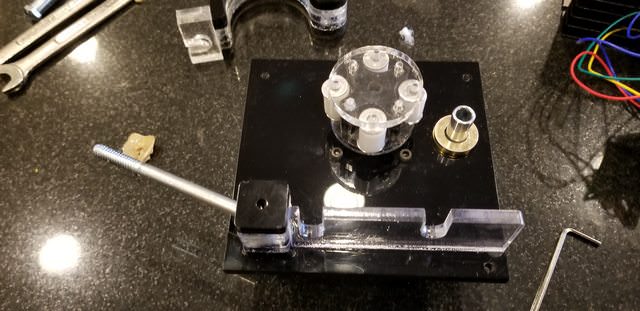
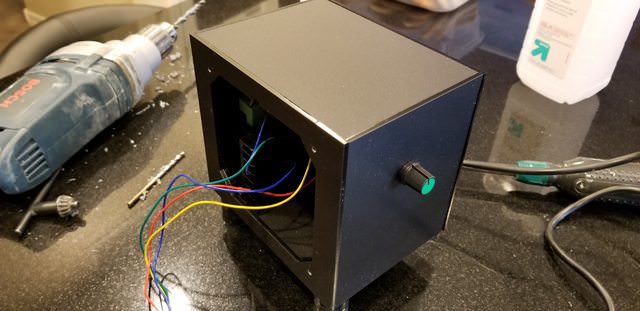
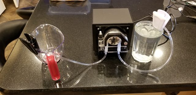
As I get settled in with my new tank, aspirations of having a full blown SPS dominant tank requires me to have stable alkalinity, which means I will need a calcium reactor at some point in the future. From talking with friends and reading on line, I discovered that using a pump and needle valve to control flow through the reactor is a thing of the past and most successful reefers moved to a paristaltic pump a lot like the Kamoer FX-STP pump. I started digging further and found out that quality paristaltic pumps are really pricey. The first think I thought of when I saw the prices was, "I can't justify that!"

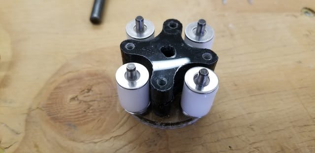
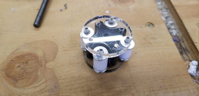
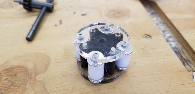
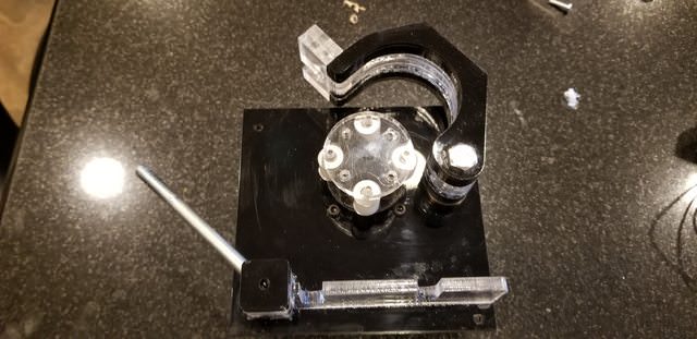
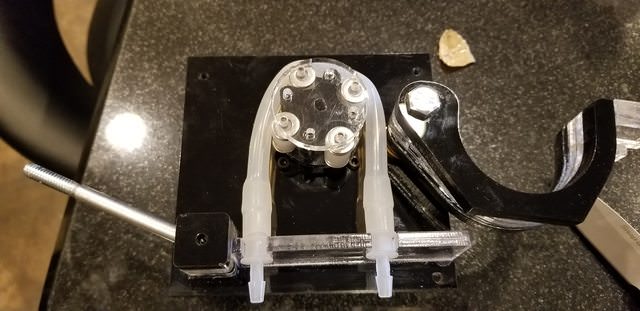
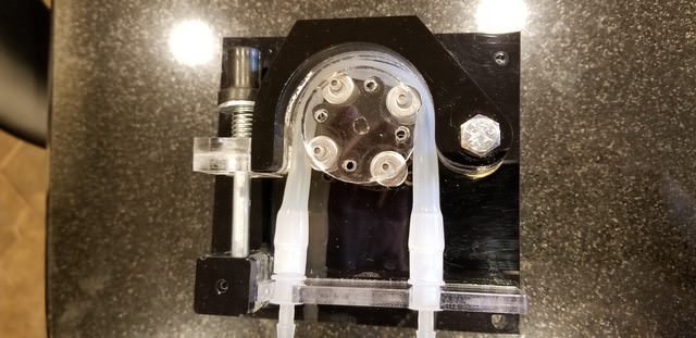
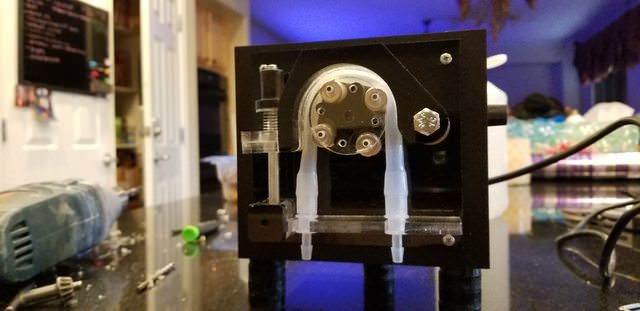
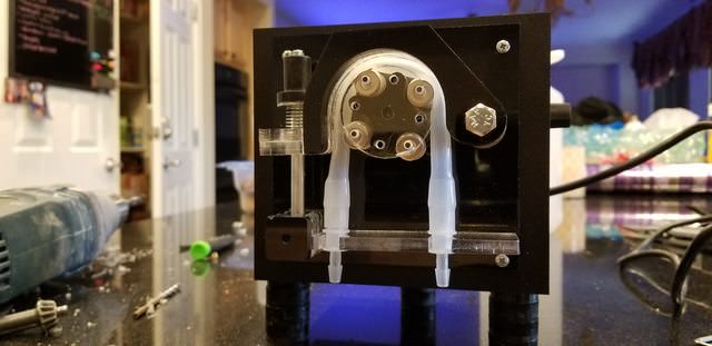
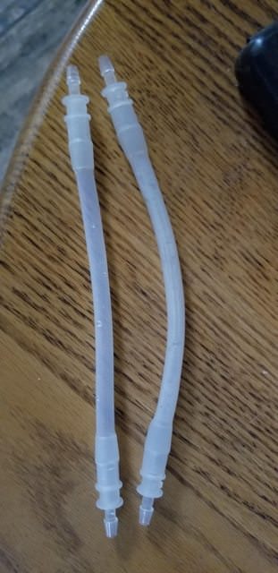
Understanding the basic concept of the pump, that it's a positive displacement pump and uses mechanical means to move liquid from 1 place to another without the liquid coming in contact with the pump itself.

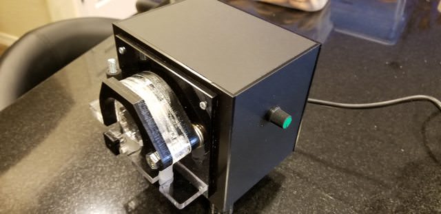
Using the kamoer as a jumping off point I set some goals. The pump has to be:

1. accurate with dispensing fluid
2. robust enough to run nonstop
3. controllable, able to adjust fluid output throughout many different ranges (motor RPM or ml per minute)
4. able to run for 6 months without significant changes in output
5. able to get parts online with the ease
6. come in at a cost far below retail pumps

With all that in mind I started thinking about what motor to use? For accuracy, you can't beat a stepper motor, you can control very accurately the number of rotations and essentially program exact dosing regiment, a lot like how the neptune DOS works (at least I think they use a stepper motor design).

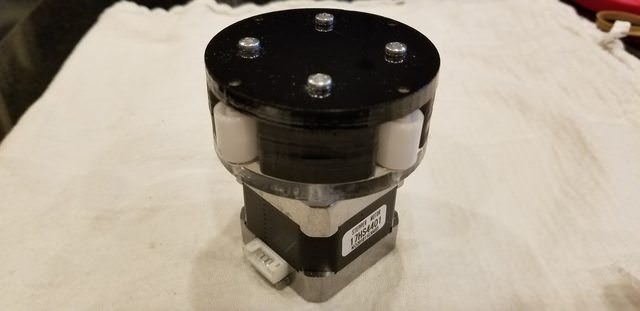
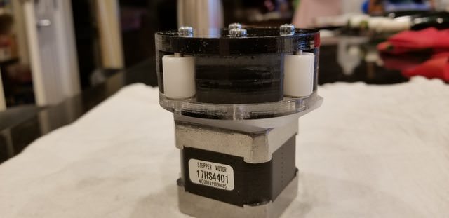
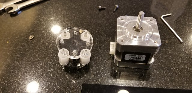
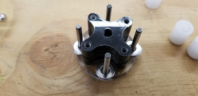
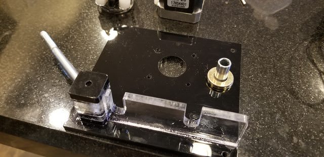
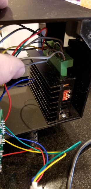
Down that rabbit hole I went. Outside of the basic concept, I didn't realize there were so many different stepper motor and applications, you have a unipolar, bipolar, Nema ratings, torque ratings... I was overwhelmed. I sought help on another forum and was able to narrow it down. I hopped on amazon and found one that seems like it would fit my needs. Side note, if you know me, I'm a touchy feely guy that needs to see and play with and sometimes take apart something to know weather or not it's going to work, pictures and data sheets can only go so far. I ordered a motor, driver and controller from amazon $37. And started playing with it.
 
OP
OP
Sisterlimonpot

Sisterlimonpot

Effortless Perfection
View Badges
Joined
Jul 15, 2009
Messages
3,854
Reaction score
7,897
Location
Litchfield Park
Rating - 0%
0   0   0


Ultimately I want to be able to control this with an Arduino, but for now I want to be able to play with it. The driver is pretty primitive in the fact that it has 6 dipswitches that allow you to set how many steps and pulses you want per revolution which boils down to a range of RPM and torque, You can also set how much current you want going to the motor, more current equals more torque but also more heat, moving forward I had to be careful with that.

I set off with making a large pump head to move large quantities of water quickly and designed the pump to have a 2.7" diameter rotary head:

8gbKI1sl.jpg


I designed all of this out or acrylic using a C02 laser to cut acrylic in layers. Ideally a 3D printer would be the best tool for the job, but I have to use what's available to me.

CPkHga1l.jpg


After putting the head unit together, I got to play with it:


I quickly realized that this stepper motor didn't have the rotational torque requirements that was needed for this diameter pump. When I tried to manually squeeze the tube with the stationary frame, the resistance was too great and bogged the motor.


What do I do from here? I see that I only had a handful of options,

1. Get a bigger motor
2. Incorporate a gear box to increase torque
3. Find a paristaltic tube with a thinner wall (easier to squish)
4. Make a smaller pump

Each had their pros and cons, I ended up scrapping the larger pump and making a smaller rotary head which obviously lower the motors torque requirements.

ofkWpcNl.jpg


This head had a 1.7" diameter.

F61a2ZTl.jpg


WbnmU7Jl.jpg


TSMaEIAl.jpg


b0k9yfwl.jpg
 
OP
OP
Sisterlimonpot

Sisterlimonpot

Effortless Perfection
View Badges
Joined
Jul 15, 2009
Messages
3,854
Reaction score
7,897
Location
Litchfield Park
Rating - 0%
0   0   0
I already designed the mounting plate for the larger pump so it was easy to cut a new one with new locations of certain parts.

uMPIEYjl.jpg


Installed the motor and pump head

kR2hbwVl.jpg


Installed the pivoting frame

1rhUMR6l.jpg


Right now I'm simply using silicon tubing 6mm ID 9mm OD. In the future I plan to use a more durable tube.

Ywt6Prrl.jpg


Clamp it all down with the spring and nut

he7s5hEl.jpg


After getting it all together I wanted to test it out:


OP
OP
Sisterlimonpot

Sisterlimonpot

Effortless Perfection
View Badges
Joined
Jul 15, 2009
Messages
3,854
Reaction score
7,897
Location
Litchfield Park
Rating - 0%
0   0   0
After verifying that it was going to work, I designed and cut out the pieces to make the box

Huwu6h9l.jpg


hQzpZ9zl.jpg


Tapped all the holes

f5csSq9l.jpg


Installed the driver

MM7RXiUl.jpg


I didn't get a good picture of installing the controller but here's where the control knob sits

5rhZ6V4l.jpg


Put the plate on

gh1VkKCl.jpg


ulXSk91l.jpg
 
OP
OP
Sisterlimonpot

Sisterlimonpot

Effortless Perfection
View Badges
Joined
Jul 15, 2009
Messages
3,854
Reaction score
7,897
Location
Litchfield Park
Rating - 0%
0   0   0
Completed assembly

dUllwIll.jpg


Now it's time to test how quickly I can move 500ml of water.

SCmXyShl.jpg


For the most part this was on the low setting about 1:30 in I ramp up the speed, so you can hear and see the difference that it made.


As I explained earlier, the driver can be set to many different speeds and when a speed is selected you can only adjust the speed in a small range based on the position of the knob. I can foresee that once I get the desired range I want, I can set the dipswitches and utilize the knob to fine tune a particular amount of fluid transfer.

this particular setting, I was able to turn the dial all the way down and transfer 500ml in 1 minute 43 seconds. and turned all the way up I was able to get 500ml in just 59 seconds.

There's a lot more testing to ensure longevity, so in the meantime I put it on my ATO so that if a problem arises, I can easily detect it and it wont cause a catastrophic failure in my tank.

During this project I kept a spreadsheet of all my costs, minus cost of the acrylic, I spent $70. Not bad considering the alternative.
 

IgnatiusRath

Community Member
View Badges
Joined
Oct 16, 2018
Messages
93
Reaction score
462
Rating - 0%
0   0   0
Bookmarked and inspired! Thank you for the build on this! I picked up the Kamoer FX-STP pump to use on my CaRx and I've been running it as my ATO while I finish building the reactor setup. Made me not want to go back to my old ATO, but I'm not spending $260 for a topoff pump. This may be the ideal answer. If you do a 3d printed version, would you be putting the build files out to share? I have access to a couple 3d printers, but my skills aren't yet up to designing anything quite this level yet.
 
OP
OP
Sisterlimonpot

Sisterlimonpot

Effortless Perfection
View Badges
Joined
Jul 15, 2009
Messages
3,854
Reaction score
7,897
Location
Litchfield Park
Rating - 0%
0   0   0
@theatrus

I thought that too, the 3D version would have their own set of concerns. The only downside to acrylic is having to bond them and then smoothing the curve where the tube gets punched by the rollers.

@IgnatiusRath
Yes, I'm a firm believer that as a collective we can make things better.

I have a different silicone tube coming in tomorrow and will have to re-do the base line test. The thought right now is to check accuracy every 30 days to see how it holds up...

As I understand it, the kamoer has a range of 1-100ml per minute. I should shoot for that setting for the calcium reactor. But as it sits, it works great for ato.
 

IgnatiusRath

Community Member
View Badges
Joined
Oct 16, 2018
Messages
93
Reaction score
462
Rating - 0%
0   0   0
@theatrus

I thought that too, the 3D version would have their own set of concerns. The only downside to acrylic is having to bond them and then smoothing the curve where the tube gets punched by the rollers.

@IgnatiusRath
Yes, I'm a firm believer that as a collective we can make things better.

I have a different silicone tube coming in tomorrow and will have to re-do the base line test. The thought right now is to check accuracy every 30 days to see how it holds up...

As I understand it, the kamoer has a range of 1-100ml per minute. I should shoot for that setting for the calcium reactor. But as it sits, it works great for ato.

Open source is the way to a free future man, firm believer in it!

The Kamoer actually goes up to 120 ml/min and I think it's a pretty solid range really. I've been running mine around 60-70 ml/min as a top off, mostly so I can catch it to shut off and make adjustments as I mess with the tank since I'm dialing in new changes lately.


McPuff

Valuable Member
View Badges
Joined
Dec 11, 2018
Messages
1,330
Reaction score
1,521
Location
Plymouth, MI
Rating - 0%
0   0   0
@Sisterlimonpot you are incredible in all your DIY ventures. Seriously impressive. I'm looking forward to seeing how this works out for you. I've been contemplating the Kamoer pump to better stabilize my Ca reactor. The manifold (off my return pump) is pretty consistent but needs some tweaking once in a while. This is probably the last piece of the puzzle for me, save for a tweak or two to my flow (e.g., narrow flow for my tunze 6105 to improve flow).
 
OP
OP
Sisterlimonpot

Sisterlimonpot

Effortless Perfection
View Badges
Joined
Jul 15, 2009
Messages
3,854
Reaction score
7,897
Location
Litchfield Park
Rating - 0%
0   0   0
The silicone tubing I am currently using has an inner diameter (ID) of 6mm and an outer diameter (OD) of 9mm. When making the pump, I took that into consideration when I designed the pivoting frame, I left a 3.048mm gap between the rollers and frame. this morning the new tube showed up with 6mm ID 8mm OD. The thinner wall of the tube prevented the roller to pinch off the tube to prevent a siphon. I would have to cut a new pivot frame to accommodate the new tube. The only time it would pinch would be if the motor stopped with a roller sitting at the 12 o'clock position. I didn't have the time to cut it, so I ended up taking the pivot frame off and put it in the oven for 15 minutes at 200 degree, it made it pliable enough to bring the sides in 1mm. That didn't work so well because the position of the right side of the frame didn't change in reference to the rotary head, in other words, it didn't pinch off the smaller tube.

With that in mind I still made one out of the thinner walled tube and timed it to feed 500ml.

SpMV3nPl.jpg


6mm x 9mm Low Setting 1:37
6mm x 8mm Low Setting 2:09

6mm x 9mm High Setting 1:05
6mm x 8mm High setting 1:33

For the time being I will keep with the 6mm x 9mm for the tests, and will make this my base line, in 4 weeks I will run tests again and hope for consistency.

Keeping in mind that this is just a prototype and hope to get input for improvements.

I just happened to be home when the pump kicked on, it's a bit noisy, I suspect it's from the washers on the rotary head. But you can also hear noise from the stepper motor too, and that will be something that can't really be changed unless we find a quieter motor.


BigJohnny

2500 Club Member
View Badges
Joined
Aug 27, 2015
Messages
3,707
Reaction score
2,471
Location
North Carolina
Rating - 0%
0   0   0
Great job. You should see if there is a way you can incorporate and LCD display that shows the rpms or figure out how to convert to ml/min and display that!
 

Caring for your picky eaters: What do you feed your finicky fish?

  • Live foods

    Votes: 14 26.4%
  • Frozen meaty foods

    Votes: 44 83.0%
  • Soft pellets

    Votes: 7 13.2%
  • Masstick (or comparable)

    Votes: 4 7.5%
  • Other

    Votes: 2 3.8%
Back
Top