Optical Sensor Alternative for FMM - Contactless Liquid Level Sensor

puffy127

Valuable Member
View Badges
Joined
Feb 2, 2016
Messages
1,095
Reaction score
1,070
Rating - 0%
0   0   0
I was looking into adding optical sensors to monitor my 2-part dosing container levels, but adding 2 OS-1Ms at $35 a pop wasn't appealing, especially since I just had to replace a OS-1 that died on me after just over 1 year of use. Ebay/amazon have identical looking optical sensors for much cheaper, but I wasn't sure if they would work or how they could connect to the FMM. Then I came across this thread: https://www.reef2reef.com/threads/apex-dos-diy-level-switch.246352/ (the bulk of which is not directly applicable) but in there, other users successfully attached 3.5mm TRRS connectors to these sensors and had them working in their FMMs. Some in that thread also mentioned contactless liquid level sensors working. Intrigued, I embarked upon this path and can happily report that indeed these contactless liquid level sensors can work! Much thanks to all those that pioneered this.

This is the sensor I am referring to. You can find these on ebay/amazon by searching for contactless liquid level sensor or non-contact liquid level sensor:

410rjq5a9DL.jpg

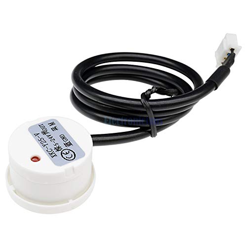
I got mine for about $8 from a US dealer on ebay, but you can get them for much cheaper if you are willing to wait for shipping from China.
You just stick these on the outside of your liquid container and it can detect the liquid level. No worries about water droplets, salt creep, bent cables, etc. that plague the optical sensors.

You cut the connector off, and strip the cables. You then attach the cables to a 3.5mm TRRS connector. If you are skilled in soldering, then just get a typical TRRS 3.5 mm connector. If not, you can do like me and get one of these (search for 3.5mm 4 Pole TRRS Male to 4 Screw Terminal Female):
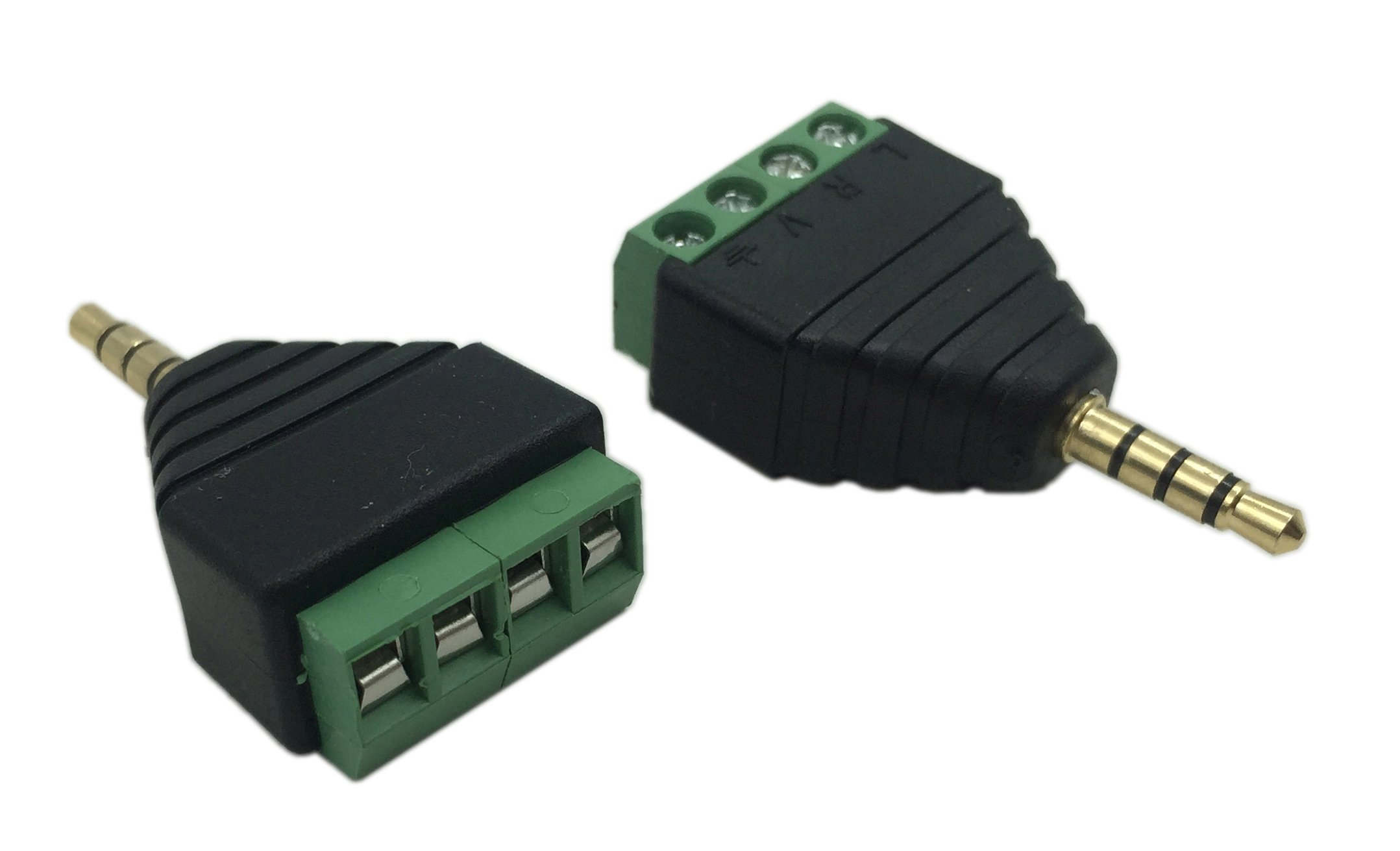
710-iWYucNL.jpg

I got a 2-pack for about $7 on amazon ().

Now, which wires do you connect to which plug? From the 4-screw terminal above, from tip (furthest away from base) to sleeve (closest to base), it goes L, R, V, ground.

From the sensor, the yellow wire is signal, which goes to the tip (L). The black wire is M, which goes to (R). The Brown wire is power, which goes to (V), and the blue wire is ground. I read another user stating that M was not used and that it might be for sensitivity adjustments. I found that M affects the polarity of the signal, so this would affect whether FMM reads Closed or Open when liquid is detected. This is how I wired mine:


20190913_161336.jpg


The problem with the FMM is that the jack is recessed in the housing, and many 3.5mm connectors are too fat to fully insert the jack. I solved this by getting a thin 3.5mm TRRS extension, which I needed anyways since the sensor cable is pretty short. This one from amazon works well ():

71GPUzwIgoL.jpg


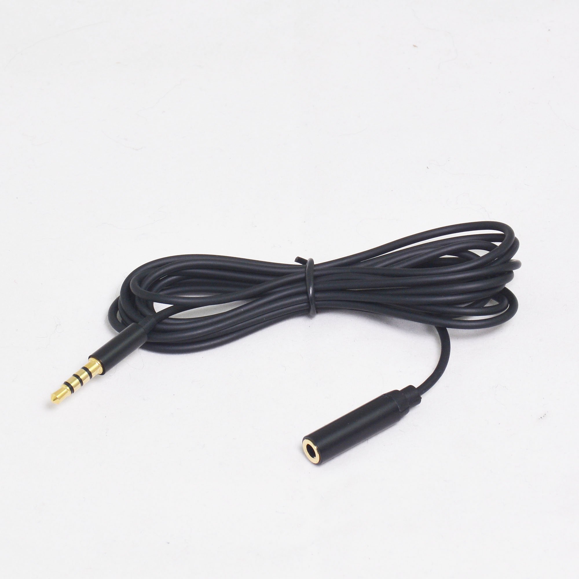
I got this 2-pack for $8.

Plug into the FMM, and configure it as an optical sensor. Make sure the sensor works, the red signal lights up when liquid is detected in a container and goes away when liquid is not detected in a container (or below and above the liquid line in a container). In apex, If you wired M, the switch should read as Closed when liquid is detected and Open when no liquid is detected. If you did not wire M, then it will read Open when liquid is detected and Closed when no liquid is detected. Then just stick this on your container and program away.

Here is mine:


20190913_164841.jpg


I now need to find a better adhesive. I used double-sided tape and it seems to work for the time being, but I would like something a little stronger, but less permanent than super glue. You should test whatever adhesive you will use to make sure the sensor will still detect liquid through it.

Warning: I am using this solely to alert me when my 2-part containers get low. I have no idea how reliable these sensors are and if you try this on mission-critical applications like controlling an ATO pump and it fails on you, you do so at your own risk.

Total: ~$23 for 2 sensors and cables, so ~$12 each. Again, if you can solder and are willing to wait on China shipping, you can do it for much cheaper. If the sensor fails, you only need to replace the sensor at ~$8 (you don't need to replace the cables).
 

rkpetersen

walked the sand with the crustaceans
View Badges
Joined
Sep 14, 2017
Messages
4,528
Reaction score
8,865
Location
Near Seattle
Rating - 0%
0   0   0
This is wonderful information. Going to bookmark this.
Also, an FYI - The OS-1 has been redesigned recently and should no longer leak/fail.
 

radiata

Valuable Member
View Badges
Joined
Nov 2, 2015
Messages
1,089
Reaction score
764
Rating - 0%
0   0   0
Nice post. Just wondering what kind of testing you did with them before you put them on-line...
 
OP
OP
puffy127

puffy127

Valuable Member
View Badges
Joined
Feb 2, 2016
Messages
1,095
Reaction score
1,070
Rating - 0%
0   0   0
Not much, just took a cup of water and held it up to the cup above and below the water line and verified that the red signal lit up and the FMM switch toggled Closed and Open in fusion (albeit with a delay). You actually don't even need a cup of water, you can just hold it up to your hand. Also on the container itself, you can do the same.
 

Sleepydoc

Valuable Member
View Badges
Joined
Apr 10, 2017
Messages
1,423
Reaction score
1,266
Location
Minneapolis, MN
Rating - 0%
0   0   0
Cool!
how accurate are these sensors? the Optical sensors can sense a level change of ~⅛" From the description, it seems like they would be good for things like a dosing container or an ATO reservoir, but perhaps not a level sensor for an ATO.

I've had better luck than some with my Apex Optical Sensors. As someone mentioned, they changed the design so the new ones are supposedly more reliable. I haven't heard anything either way whether that's true or not. Somewhere I read that the problem was due to the plastic casing developing cracks that allowed salt to cause corrosion - either way, a living saltwater tank is not the most hospitable environment for sensors, so having a non-contact sensor is nice. Assuming you keep the glass clean...
 
OP
OP
puffy127

puffy127

Valuable Member
View Badges
Joined
Feb 2, 2016
Messages
1,095
Reaction score
1,070
Rating - 0%
0   0   0
It's hard to know how accurate they are in sensing water level changes because it's not exactly clear where the sensor line is. It seems like the sensor line is in the middle of the device (i.e. when the water level drops to below the halfway point of the device, that's when it changes from detect to not detect), but I've not tested it for ATO applications. I would not recommend it for that purpose without extensive testing. Supposedly there is a sensitvity adjustment dial if you take off the cover, but I have not looked into or tested that.

I found this description:

SENSITIVITY ADJUSTMENT:
1. Open the back cover of the sensor head, use small screwdriver to adjust the sensitivity knob
2. If counter clockwise rotate the knob, it will increase sensitivity, otherwise, it will decrease the sensitivity.

A9R7ezxl9_cu2bl6_750.jpg
 
OP
OP
puffy127

puffy127

Valuable Member
View Badges
Joined
Feb 2, 2016
Messages
1,095
Reaction score
1,070
Rating - 0%
0   0   0
Here is a diagram and description which helped me with the wiring:

AJWX_1_201908151484459059.jpg


CONNECTION INTRODUCTION:
 Brown wire (VCC); power 5-24V (connects power positive)
 Yellow (OUT); signal output
 Black wire (M); output level (positive output or negative output) control. When black wire connects high level, yellow wire is positive output signal wire; if there is induction, it will output high level; if there is no induction, it will output low level (NPN-disconnect) When black wire connects low level, yellow wire is negative output signal wire; if there is induction, it will output low level; if there is no induction, it will output high level
 Blue wire (GND); ground wire (connects power negative)
 

Dbasileccim

Community Member
View Badges
Joined
May 22, 2014
Messages
84
Reaction score
82
Location
Melbourne, Florida
Rating - 0%
0   0   0
I know this is a really old thread but I am having a bit of a problem making this work. Could you make a simple sketch of sensor wires (by color ) connecting to the Segments of the pin connector to the fmm. I am not consistently getting a change of state every way I wire it and occasionally whatever I am doing is affecting the other ports on the fmm. Any help would really be appreciated! Thanks.
 
OP
OP
puffy127

puffy127

Valuable Member
View Badges
Joined
Feb 2, 2016
Messages
1,095
Reaction score
1,070
Rating - 0%
0   0   0
I know this is a really old thread but I am having a bit of a problem making this work. Could you make a simple sketch of sensor wires (by color ) connecting to the Segments of the pin connector to the fmm. I am not consistently getting a change of state every way I wire it and occasionally whatever I am doing is affecting the other ports on the fmm. Any help would really be appreciated! Thanks.

There is a photo in the first post showing the sensor wires going into the pin connector. You may need to enlarge the photo.
 

Dbasileccim

Community Member
View Badges
Joined
May 22, 2014
Messages
84
Reaction score
82
Location
Melbourne, Florida
Rating - 0%
0   0   0
There is a photo in the first post showing the sensor wires going into the pin connector. You may need to enlarge the photo.
Thanks, I put one together about 6 weeks ago and it works great. I bought five more and followed the directions (I thought) and could not get them to work. I'll check out the beginning of the thread. Thanks so much for responding.
 

Dbasileccim

Community Member
View Badges
Joined
May 22, 2014
Messages
84
Reaction score
82
Location
Melbourne, Florida
Rating - 0%
0   0   0
I was wondering if you would confirm what the voltage is coming out of the fmm socket on your adapter that you are using. I am having a hard time getting this to work consistently and just discovered that the power pins are at around 3.6 to 4 volts. I expected at least 5 volts and possibly 12 or 24 volts. I really appreciate it. Thanks.
 

TheHarold

5000 Club Member
View Badges
Joined
Oct 3, 2015
Messages
5,145
Reaction score
8,759
Rating - 0%
0   0   0
I was wondering if you would confirm what the voltage is coming out of the fmm socket on your adapter that you are using. I am having a hard time getting this to work consistently and just discovered that the power pins are at around 3.6 to 4 volts. I expected at least 5 volts and possibly 12 or 24 volts. I really appreciate it. Thanks.

Those common optical liquid level sensors can operate on common arduino microcontrollers, which start at 3.3v. So your reading makes sense to me.

One would want the lowest voltage possible, for sure not 12 or 24v.
 

Dbasileccim

Community Member
View Badges
Joined
May 22, 2014
Messages
84
Reaction score
82
Location
Melbourne, Florida
Rating - 0%
0   0   0
I do understand that, however, the contactless sensors and the flow sensors all run on 5 to 24 volts. I was surprised to see 3.8 and 4 volts (over the 3.3 volts of some devices and below the 5 volts of other devices. On top of that the aquabus is 12 volt system. I hope someone has as easy way to confirm the voltage of the ports on the fmm. Thanks.
 
OP
OP
puffy127

puffy127

Valuable Member
View Badges
Joined
Feb 2, 2016
Messages
1,095
Reaction score
1,070
Rating - 0%
0   0   0
Sorry, can't help with this. I am no longer using these, but never had any issues when I was using them.
 

Gophish1982

Active Member
View Badges
Joined
Jan 13, 2022
Messages
132
Reaction score
42
Location
Columbus
Rating - 100%
1   0   0
I know this is an old thread, but I just found these sensors and was wondering if anyone else has had success with them. The instructions above seem straight forward, but I’m just not sure which sensor to buy. There are several different models of these that I imagine have different uses and voltage ratings so I’m unsure of where to even start. I feel like this would be my best option to have a warning sensor/shut off when my skimmer cup is full. I bought some float switches, but the modification I would have to make to the cup lid would be pretty significant.
 

radiata

Valuable Member
View Badges
Joined
Nov 2, 2015
Messages
1,089
Reaction score
764
Rating - 0%
0   0   0
This Video was released two days ago:

NEW Neptune Systems Sensors to Keep Our Reef Tanks Safe!?​


Sleepydoc

Valuable Member
View Badges
Joined
Apr 10, 2017
Messages
1,423
Reaction score
1,266
Location
Minneapolis, MN
Rating - 0%
0   0   0
Those new sensors look cool! Peopl have been asking for an analog level sensor for years so it’s great Neptune is finally making one available. I know some people have used an ultrasonic sensor with DIY arduino/raspberry pi controllers but I don’t know how well those hold up to humidity.

The new optical sensors are a nice evolution - a bit cleaner and more coordinated like they said in the video, but assuming they don’t have the issues with the seals allowing water ingress that the V1 optical sensors had there shouldn’t be much functional difference.
 

Sleepydoc

Valuable Member
View Badges
Joined
Apr 10, 2017
Messages
1,423
Reaction score
1,266
Location
Minneapolis, MN
Rating - 0%
0   0   0
I know this is an old thread, but I just found these sensors and was wondering if anyone else has had success with them. The instructions above seem straight forward, but I’m just not sure which sensor to buy. There are several different models of these that I imagine have different uses and voltage ratings so I’m unsure of where to even start. I feel like this would be my best option to have a warning sensor/shut off when my skimmer cup is full. I bought some float switches, but the modification I would have to make to the cup lid would be pretty significant.
I bought a couple of them for a DIY mixing station controller. I can’t comment directly on the integration with an Apex but in my experimenting I did find they need to be solidly adhered to the surface. The reason I bring this up is that I’m not sure how well they’d work for a circular skimmer cup.

Does your skimmer allow for an external drain? What I ended up doing was draining my skimmate cup directly to a flat jug i got from BRS and installing a float switch in the top of the jug. Works much better and is easier to empty, too.
 

Gophish1982

Active Member
View Badges
Joined
Jan 13, 2022
Messages
132
Reaction score
42
Location
Columbus
Rating - 100%
1   0   0
That is a fantastic idea. I had already kind of thought about, one day, when I’m in a different place and my aquarium is on the first floor, just having the skimmer drain through to the basement and out a drain. I don’t know why I didn’t think of having it drain to a bucket. I was even looking at those expensive skimmate lockers! This is going to work perfectly and only cost me about $15 at the hardware store. Thanks for connecting the dots for me!
 

Sleepydoc

Valuable Member
View Badges
Joined
Apr 10, 2017
Messages
1,423
Reaction score
1,266
Location
Minneapolis, MN
Rating - 0%
0   0   0
That is a fantastic idea. I had already kind of thought about, one day, when I’m in a different place and my aquarium is on the first floor, just having the skimmer drain through to the basement and out a drain. I don’t know why I didn’t think of having it drain to a bucket. I was even looking at those expensive skimmate lockers! This is going to work perfectly and only cost me about $15 at the hardware store. Thanks for connecting the dots for me!
one potential disadvantage of draining the skim mate directly to a floor drain is that it can essentially be an infinite sink to drain water from your tank. Of all the equipment we use, skimmers are probably the most finicky. Having a jug with a float switch essentially limits the drain to the size of the jug so if your skimmer goes haywire you don't have to worry about it dumping 30 gallons down the drain.

Another tip - when you connect the float switch, set it up so it's normally closed and then turns open when the jug is full. That way if something happens and the float switch gets disconnected the default will be for Apex to turn off the skimmer. I have mine set up so I can unplug the wire to make emptying the jug easier. Once while we were out of town my dad was watching the tank and forgot to plug it in. At that time I had the switch reversed and the skimmer chose that night to overflow, filling the jug and flooding my sump. Arrgh! I changed the float switch after that to the configuration described above to give an extra layer of secutity
 

Algae invading algae: Have you had unwanted algae in your good macroalgae?

  • I regularly have unwanted algae in my macroalgae.

    Votes: 44 35.2%
  • I occasionally have unwanted algae in my macroalgae.

    Votes: 27 21.6%
  • I rarely have unwanted algae in my macroalgae.

    Votes: 9 7.2%
  • I never have unwanted algae in my macroalgae.

    Votes: 10 8.0%
  • I don’t have macroalgae.

    Votes: 31 24.8%
  • Other.

    Votes: 4 3.2%
Back
Top