reef-pi :: An opensource reef tank controller based on Raspberry Pi.

OP
OP
Ranjib

Ranjib

7500 Club Member
View Badges
Joined
Apr 16, 2016
Messages
9,843
Reaction score
17,056
Location
Pleasant Hill, Concord
Rating - 0%
0   0   0
Hi Ranjib,
I've been lurking on this thread for a week or so and I'm definitely going to get a raspberry pi and use reef pi to control my new tank.
i haven't read all 369 pages though ... do i need to, or is there a resource somewhere that i can catch up ?
also i'm probably going to get the "pi 3b+" does reef pi work on this latest version ?
and one last thing plz, do i need to get the touch screen or can i log in remotely over wifi ?

thanks for all you effort in this you seem to have got a really good community going here :)
Welcome to reef2reef and thank you for considering reef-pi.
reef-pi works just fine on pi 3b+, I have personally tested this and have one of my dev build running . You don’t need touch screen , in fact none of my build uses any touch screen and no GUI, they all run headless . You also don’t need to read through this whole thread , it’s mostly used for ongoing development and for any out of band help other may need , since this thread has very high visibility with a whole bunch of folks helping each other out. You can just go through the adafruit guides (enlisted in the very first post in this thread ) and that should get you started, and then if you have any issue ask here or even better start a dedicated thread in diy section , that will keep things coherent as well as others can learn from it
Godspeed
 

Mandelstam

Well-Known Member
View Badges
Joined
Oct 29, 2017
Messages
688
Reaction score
1,117
Location
Malmö, Sweden
Rating - 0%
0   0   0
Hey everyone!

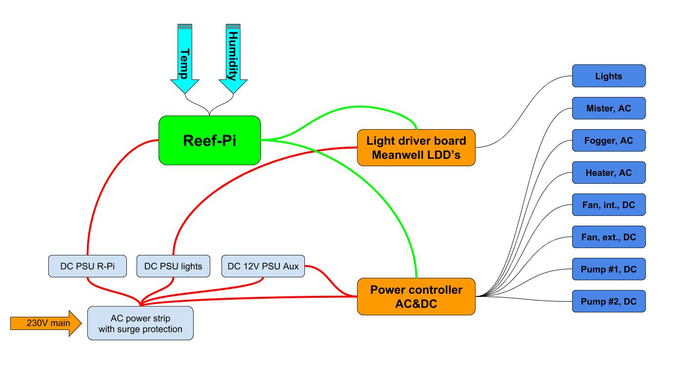
I thought my first Reef-Pi build was going to be for an actual reef but now it looks like it's going to be controlling a big 340 gallon rainforest vivarium. I've been trying to sketch up a basic schematic of everything just to try and wrap my head around how it's all going to be put together. Btw, Google Drawings are really handy sometimes.

1HWru7y.jpg


As it's not going to be controlling a reef, some of the features won't be used (ATO, pH-probe, etc). The main thing it will handle is the light cycle and managing the equipment via the power controller.
One thing I've been wondering a bit about is how to divide everything up in physical boxes. Could I squeeze everything into one single bigger chassi, etc? But what I think I'm going to do is divide it up into three main boxes.
  • Reef-Pi, with inputs from sensors and outputs for lighting and power controller
  • Lighting controller, with driver board. PWM input from Reef-Pi and output to light
  • Power controller, signal input from Reef-Pi and relays for 230V AC and 12V DC outlets. Input with 12V DC and 230V AC from PSU and mains.
I know Reef-Pi doesn't support humidity monitoring at the moment, and I'm just going to wait patiently for that. @Ranjib, do you have any plans or thoughts on what kind of sensor you'll be aiming for?

Another questin for you Ranjib, I know you're also planning to add a controller for wave makers in the future. When that's implemented, could that be used to, instead of wave makers, control a 12V PWM computer fan? I'm not sure how wave makers are controlled. I'm going to have fan powered internal air circulation so it's quite analogous to wave makers, just a different media being pushed around. In the meantime I'm just going to control it via the power controller and maybe add a small potentiometer to control the speed if I don't want to run it at full speed. What I would like to do however is to run it at lower speed most of the time and then have surges at full speed at some intervals connected to misting schedule etc.
 
OP
OP
Ranjib

Ranjib

7500 Club Member
View Badges
Joined
Apr 16, 2016
Messages
9,843
Reaction score
17,056
Location
Pleasant Hill, Concord
Rating - 0%
0   0   0
Hey everyone!

I thought my first Reef-Pi build was going to be for an actual reef but now it looks like it's going to be controlling a big 340 gallon rainforest vivarium. I've been trying to sketch up a basic schematic of everything just to try and wrap my head around how it's all going to be put together. Btw, Google Drawings are really handy sometimes.

1HWru7y.jpg


As it's not going to be controlling a reef, some of the features won't be used (ATO, pH-probe, etc). The main thing it will handle is the light cycle and managing the equipment via the power controller.
One thing I've been wondering a bit about is how to divide everything up in physical boxes. Could I squeeze everything into one single bigger chassi, etc? But what I think I'm going to do is divide it up into three main boxes.
  • Reef-Pi, with inputs from sensors and outputs for lighting and power controller
  • Lighting controller, with driver board. PWM input from Reef-Pi and output to light
  • Power controller, signal input from Reef-Pi and relays for 230V AC and 12V DC outlets. Input with 12V DC and 230V AC from PSU and mains.
I know Reef-Pi doesn't support humidity monitoring at the moment, and I'm just going to wait patiently for that. @Ranjib, do you have any plans or thoughts on what kind of sensor you'll be aiming for?

Another questin for you Ranjib, I know you're also planning to add a controller for wave makers in the future. When that's implemented, could that be used to, instead of wave makers, control a 12V PWM computer fan? I'm not sure how wave makers are controlled. I'm going to have fan powered internal air circulation so it's quite analogous to wave makers, just a different media being pushed around. In the meantime I'm just going to control it via the power controller and maybe add a small potentiometer to control the speed if I don't want to run it at full speed. What I would like to do however is to run it at lower speed most of the time and then have surges at full speed at some intervals connected to misting schedule etc.

Your sketch looks perfect to me. I want to add support for humidity sensor as well, mainly because I want to explore the effect of humidity on water evaporation (ATO usage), but since its not a critical thing its not a top priority. I'll try to work on it on 3.0, but can not gurantee, if high priority things get delayed (clustering, wave maker, calibration, IO expander etc), it will be dropped :-( . But its definitely on my radar, and if someone else is willing to code for this, I am happy to include it in 3.0. Currently I am thinking of choosing something based on i2c , e.g. AM2315, Si7021 or HTU21DF.

My recommendation will be to breakout the entire build into smaller housings isolating the AC and DC components (relays vs brain), as well as components that may need to be located at specific places (like doser) and run connector wire in between (choose hdmi or db9 or cat5). This make thing safer, isolated failures and if circuit complexity bites you, you can simply split them apart by adding individual Pi's to them (remember clustering is coming in 3.0). This gives you incremental benefit of the build as time goes by and does not force you to think about the whole thing upfront, which has been very hard for most of us.

reef-pi is not really aware of what physical hardware is connected, and entirely relies on the builder's provided configuration. Which means you can just model a fan as light and control its speed using the light UI, and turn it on and off with a relay and model that as an equipment. In short this will allow you to both control the fan via temperature controller as well as tuning the fan speed using the light ui using fixed or auto or diurnal profiles. Its not nice, but its certainly possible.
I hope this answer your question, if you build a reef-pi controller start with the guides mentioned in the very first post in this thread and ask help here or start a build thread :)
 
OP
OP
Ranjib

Ranjib

7500 Club Member
View Badges
Joined
Apr 16, 2016
Messages
9,843
Reaction score
17,056
Location
Pleasant Hill, Concord
Rating - 0%
0   0   0
@Ranjib when you say clustering do you mean connecting multiple rpi modules together? One of the reasons I am building my doser and ph all into one build (doser pumps will be remote) is I want to have one ipaddress and one dashboard for everything
Ability to access and control different reef-pi from a single place. Unified dashboard etc. https://github.com/reef-pi/reef-pi/issues/621
 

Mandelstam

Well-Known Member
View Badges
Joined
Oct 29, 2017
Messages
688
Reaction score
1,117
Location
Malmö, Sweden
Rating - 0%
0   0   0
Your sketch looks perfect to me. I want to add support for humidity sensor as well, mainly because I want to explore the effect of humidity on water evaporation (ATO usage), but since its not a critical thing its not a top priority. I'll try to work on it on 3.0, but can not gurantee, if high priority things get delayed (clustering, wave maker, calibration, IO expander etc), it will be dropped :-( . But its definitely on my radar, and if someone else is willing to code for this, I am happy to include it in 3.0. Currently I am thinking of choosing something based on i2c , e.g. AM2315, Si7021 or HTU21DF.

[...]

I hope this answer your question, if you build a reef-pi controller start with the guides mentioned in the very first post in this thread and ask help here or start a build thread :)

Thanks a million Ranjib! Monitoring humidity isn't crucial as it would only be for monitoring purposes but it definitely would be nice. I understand that there are other things with higher priority. But if anyone wants to give it a shot and need some help during testing it I'm all game! Reef-pi can be used as a powerful controller for terrariums and vivariums just as it is, but with humidity monitoring added it wouldn't have any restrictions in that area.

And yes, I guess I could hook the fan up as a light basically, how come I didn't think of that?! :)

Clustering seems nice! Would that mean that I could use a R-Pi 3 as a main board to get the GUI and then use zeroes for the added modules?
 
OP
OP
Ranjib

Ranjib

7500 Club Member
View Badges
Joined
Apr 16, 2016
Messages
9,843
Reaction score
17,056
Location
Pleasant Hill, Concord
Rating - 0%
0   0   0
Thanks a million Ranjib! Monitoring humidity isn't crucial as it would only be for monitoring purposes but it definitely would be nice. I understand that there are other things with higher priority. But if anyone wants to give it a shot and need some help during testing it I'm all game! Reef-pi can be used as a powerful controller for terrariums and vivariums just as it is, but with humidity monitoring added it wouldn't have any restrictions in that area.

And yes, I guess I could hook the fan up as a light basically, how come I didn't think of that?! :)

Clustering seems nice! Would that mean that I could use a R-Pi 3 as a main board to get the GUI and then use zeroes for the added modules?
yes.
 

Dave's Reef

Active Member
View Badges
Joined
Nov 4, 2018
Messages
102
Reaction score
150
Rating - 0%
0   0   0
Well guys I may have cooked my Pi. I was adding another 2 channels to control more outlets and my have shorted 12v to the output gpio pin and after a few attempts I was able to get the Pi to reboot and I had to reinstall Reef-pi to get it to load and now not I/O work at all. I have another Pi on the way tomorrow (Thanks Amazon Prime) I am just wanting to know if that was actually my issue and should i replace everything to be safe I have two PCA9685, also the parts to build another outlet controller and lighting controller.

Thank you
PS. I know I should have shut it down but the IP seems to change every time I do and I was being lazy and didnt want to look it up again
 

MaccaPopEye

Well-Known Member
View Badges
Joined
Jan 5, 2016
Messages
697
Reaction score
1,232
Rating - 0%
0   0   0
I am soaking up all these informations :)
A quick google search revealed there are few UL-94 rated filament, such as this one: https://www.3dxtech.com/firewire-flame-retardant-abs-filament-1kg/
Yeah it looks like ABS needs additives to make it fire retardant like this one, and it would be quite strong but is also very expensive and very hard to print (especially large flat pieces). It also looks like some PLA and PETG filaments don't catch fire and will just melt, but I can't find any that are specifically UL-94 rated.

I'll continue researching the 3D printed enclosure fire risks and report back in the thread I started :)
 

ScottBrew

Active Member
View Badges
Joined
Oct 17, 2018
Messages
385
Reaction score
865
Location
Dunedin Florida
Rating - 0%
0   0   0

MaccaPopEye

Well-Known Member
View Badges
Joined
Jan 5, 2016
Messages
697
Reaction score
1,232
Rating - 0%
0   0   0
Rather than mess with relays, wiring, and fire safety, why not use an already packaged device that should meet all your needs.

https://www.amazon.com/Iot-Relay-Enclosed-High-Power-Raspberry/dp/B00WV7GMA2
In addition to having one always on, it appears that it only has 1 relay inside so you can't really control the 3 others. It's either 2 are on and 1 is off, or 1 is on and 2 are off (plus the 1 always on).

I think for those in the US the ADJ power strip is probably the best and safest option but it won't help people outside the US :)
 

JDowns

Valuable Member
View Badges
Joined
Oct 6, 2017
Messages
1,223
Reaction score
2,671
Location
Phoenix
Rating - 0%
0   0   0
In addition to having one always on, it appears that it only has 1 relay inside so you can't really control the 3 others. It's either 2 are on and 1 is off, or 1 is on and 2 are off (plus the 1 always on).

I think for those in the US the ADJ power strip is probably the best and safest option but it won't help people outside the US :)

Good point. I thought version 2 allowed for two outlets. Guess I was mistaken. How about hacking a remote setup. You could either use an FET as a switch to complete the circuit on the manual on/off switch on the outlet or use an FET as a switch to complete the circuit on the remote. If your lucky the remote is 3.3V if not then its just a matter of a voltage divider network.

https://www.amazon.com/BESTTEN-Wireless-Electrical-Automation-Certified/dp/B073RF6PJP

There are tons of these out there in all sorts of shapes and offerings. I'm sure you guys could come up with one of them that would work well. All of them will have some sort of relay circuit already built into the device.
 

sfgabe

Active Member
View Badges
Joined
Sep 7, 2018
Messages
166
Reaction score
264
Rating - 0%
0   0   0
This means reef-pi is reading it always on... I think its highly unlikely that we have a driver bug in reef-pi, and we are missing something else here, likely configuration related. Did you already shared your configuration screenshot? If not please do, connectors (inlet GPIO 8 ?? ) and ato details (check interval, control pump etc). I just tested ATO again with master (rc-2) release, and I could not find a bug. I am doing a whole lot of field testing now, and will hate to ship reef-pi with bugs like this (if it turns out) :-( . If your issue does not resolve, then I'll create a dedicated issue on this in github and I'll try to reproduce this with actual circuit. I have spare float switches, so no issue on getting this physically verified.
Just wanted to follow up on this. I got the 2 wire / pullup float switch working on GPIO 18 (which is the pin used in the latest diagram). I'm not sure why it wasn't working on GPIO 7 or 8 through reef-pi - they both worked through the python script so the pins weren't dead. In case anyone else is head-scratching about a float not working, try switching pins.
 

Des Westcott

Well-Known Member
View Badges
Joined
May 29, 2018
Messages
646
Reaction score
1,035
Location
Durban - South Africa
Rating - 0%
0   0   0
Ok. On with my lighting saga. I thought I had this figured out.

I got the Meanwell LDD700H driver connected up and the light works.

Next step is to configure the dimming....... Connected the "dim" pin on the driver to GPIO18 on the Pi.
Went to Configuration > Settings.
Enabled "Lighting"
Reboot for good measure
Went to Configuration > Connectors > Jacks and tried to declare a jack on GPIO18 using rpi as the driver

Here's where it goes south - I get the pink Box in the top right corner of the screen with "error failed to create : error invalid pin 18 http 500

Obviously I missed something basic again. Appreciate anyone putting me on the right path.

Des
 

Kampo

Active Member
View Badges
Joined
Dec 19, 2017
Messages
349
Reaction score
327
Location
South West Michigan
Rating - 0%
0   0   0
Ok. On with my lighting saga. I thought I had this figured out.

I got the Meanwell LDD700H driver connected up and the light works.

Next step is to configure the dimming....... Connected the "dim" pin on the driver to GPIO18 on the Pi.
Went to Configuration > Settings.
Enabled "Lighting"
Reboot for good measure
Went to Configuration > Connectors > Jacks and tried to declare a jack on GPIO18 using rpi as the driver

Here's where it goes south - I get the pink Box in the top right corner of the screen with "error failed to create : error invalid pin 18 http 500

Obviously I missed something basic again. Appreciate anyone putting me on the right path.

Des

Don't have the info in front of me but go back into the setup guide. Need to enable the pwm on thr gpio.
 

Caring for your picky eaters: What do you feed your finicky fish?

  • Live foods

    Votes: 18 29.5%
  • Frozen meaty foods

    Votes: 51 83.6%
  • Soft pellets

    Votes: 10 16.4%
  • Masstick (or comparable)

    Votes: 7 11.5%
  • Other

    Votes: 3 4.9%
Back
Top