


reef-pi :: An opensource reef tank controller based on Raspberry Pi.

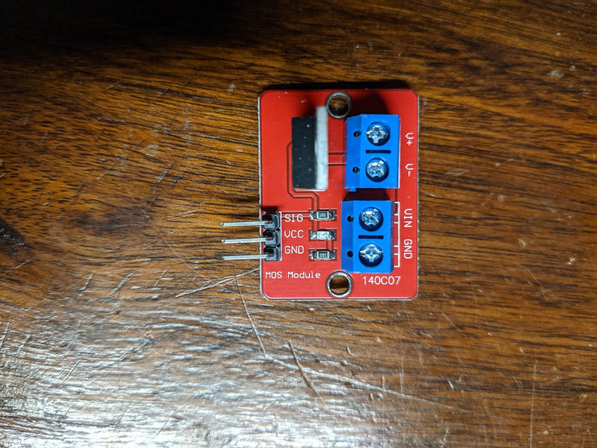
Sure here are some pics of the board, you can find them in lots of places, but for the rpi you want a logic level n channel mosfet, since you want a lower gate voltage.
PXL_20210420_151601937.jpg


Vin/gnd is power input, V+ and V- would go to the light and then the connections on the left side you would use sig and ground from the pi, you do not need to use the vcc connection.

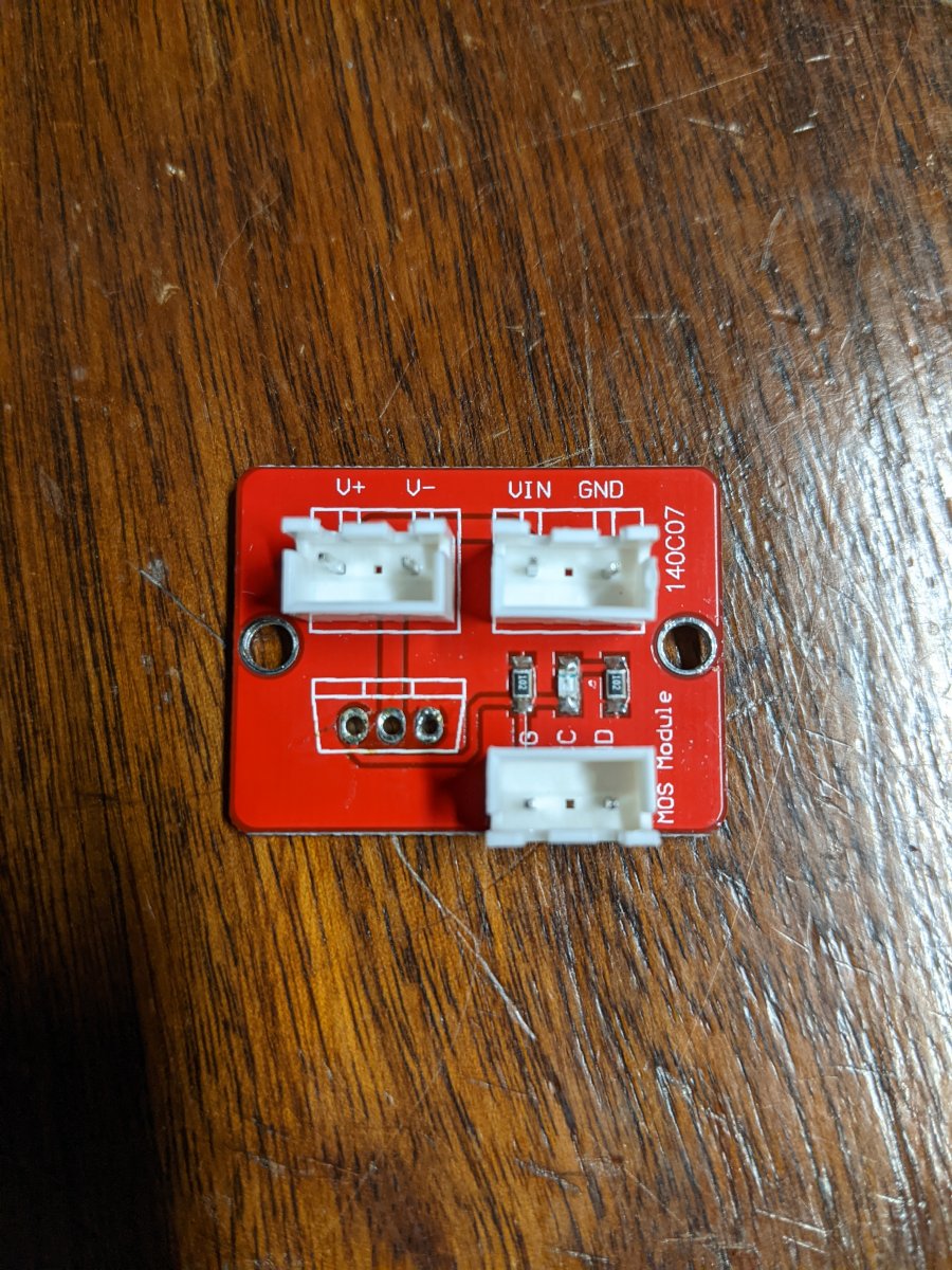
Here is how I modify them since I do not like the screw terminals:
PXL_20210420_151524316.jpg


A three pin jst-xh connector lines up with the center pin pulled. I am using the this mosfet but there are other versions - mosfet Like I said keep in mind that JST connectors are only good for 3a and you may need more depending on your light, have to run the numbers and adjust accordingly.

Here is a video showing the board being hooked up etc, lots of Robo names, lol - Robojax

Hope that helps...:)
Just doing a followup post as I reread the exchange and wanted to be sure I didn't misread something. The TO-220 from
https://www.adafruit.com/product/355 should work with the 3.3V gate voltage. The TO-220 I bought on amazon had a review that mentioned then tended to not work with rpi so I was hesitant.
 
Just doing a followup post as I reread the exchange and wanted to be sure I didn't misread something. The TO-220 from
https://www.adafruit.com/product/355 should work with the 3.3V gate voltage. The TO-220 I bought on amazon had a review that mentioned then tended to not work with rpi so I was hesitant.
TO-220 is a package that is used for higher voltage support...thats me paraphrasing it means more than that and I am sure one of the electronic guys can chime in and be a lot more specific. For the most part as an electronic noob, there are 2 types a IRF mosfet and IRL mosfet, basically a power mosfet vs logic level and for rpi based control a logic level is better suited - here is a better description - irf vs irl

That board that I show above comes with an IRF mosfet and while it works the light is really dimmed, when I switch it to a IRL mosfet the light looks normal and works as I expect it to.

I'm sure someone will come along and provide additional information. :)
 
TO-220 is a package that is used for higher voltage support...thats me paraphrasing it means more than that and I am sure one of the electronic guys can chime in and be a lot more specific. For the most part as an electronic noob, there are 2 types a IRF mosfet and IRL mosfet, basically a power mosfet vs logic level and for rpi based control a logic level is better suited - here is a better description - irf vs irl

That board that I show above comes with an IRF mosfet and while it works the light is really dimmed, when I switch it to a IRL mosfet the light looks normal and works as I expect it to.

I'm sure someone will come along and provide additional information. :)
This makes so much more sense to me know. I recently ordered some 10V regulators from my original post and realized that it also uses the TO-220 package. Your explination makes sense and is how I originally thought you were explaining yourself but then searching "TO-220" and seeing logical mosfets had me confused and spinning in circles. Maybe I will read up on them before I go and plug this in haha You are very helpful and I appreciate you explaining it to a less educated electrical tinkerer.
 
This makes so much more sense to me know. I recently ordered some 10V regulators from my original post and realized that it also uses the TO-220 package. Your explination makes sense and is how I originally thought you were explaining yourself but then searching "TO-220" and seeing logical mosfets had me confused and spinning in circles. Maybe I will read up on them before I go and plug this in haha You are very helpful and I appreciate you explaining it to a less educated electrical tinkerer.
Yeah I'm not an electronic guy either, just what I have picked up from reading here etc. The main difference is the gate voltage threshold (Vgs) for each mosfet, the power mosfets require 10v to fully open the gate vs the logic level mosfets is usually 3.3 to 5v.
 
Yeah I think if a TRS is plugged in TRRS jack the sleeve will short out the bottom ring which would be the 3 Pin mode, unfortunately I don't have a TRRS jack to verify though. If you get no voltage with TRS plugged in it sounds like is doing what it should.

Can you find another DC power point in the light? With the TRS plugged in use the sleeve for ground probe and see if it is indeed a ground.

I guess another thing you could test is connect light to adapter and see if you get 0-10v testing from the jack in light. You tested plug but how about jack when its plugged in.

Update, made another cable with a different trs plug and same response, no response. For funs and grins I inserted it into the output jack and took measurements, on one of the ends, can't remember if it was tip or ring it read 1.37v so I thought that was interesting. It does not read anything coming from the input.

I guess the next step would be to open it up, kind of reluctant to do that but not sure how else to troubleshoot it. Not real sure with doing that what I am going to be looking for, it could be that the mars aqua analaog output is just not what it wants to see, I do not have a Kessil controller on hand to verify, if I did I wouldn't need this. :)
 
Update, made another cable with a different trs plug and same response, no response. For funs and grins I inserted it into the output jack and took measurements, on one of the ends, can't remember if it was tip or ring it read 1.37v so I thought that was interesting. It does not read anything coming from the input.

I guess the next step would be to open it up, kind of reluctant to do that but not sure how else to troubleshoot it. Not real sure with doing that what I am going to be looking for, it could be that the mars aqua analaog output is just not what it wants to see, I do not have a Kessil controller on hand to verify, if I did I wouldn't need this. :)
If it's not glued together, there shouldn't be many problems with taking it apart. Some side probably is just screwed down and can be unscrewed and taken off. Just be on the lookout for cables attached between the different case parts that need to be unplugged before pulling a panel away completely or something.
 
If it's not glued together, there shouldn't be many problems with taking it apart. Some side probably is just screwed down and can be unscrewed and taken off. Just be on the lookout for cables attached between the different case parts that need to be unplugged before pulling a panel away completely or something.
Yeah understand, I'm used to taking things apart I'm just leary this time since I have $$ in some coral frags and don't want to nuke the light, lol.
 
Rob or others...

Can some one tell me regarding controlling a Kessil or the Hyperreef, requires a 0-10v. Is there any reason that I couldn't use a normal mosfet control circuit with the power source being 10v? Like what we were talking about above - https://www.reef2reef.com/threads/r...ler-based-on-raspberry-pi.289256/post-8854104

Eh I guess the more I think about it that should work but I would need to have one for each channel.

Thanks :)
 
Last edited:
Update, made another cable with a different trs plug and same response, no response. For funs and grins I inserted it into the output jack and took measurements, on one of the ends, can't remember if it was tip or ring it read 1.37v so I thought that was interesting. It does not read anything coming from the input.

I guess the next step would be to open it up, kind of reluctant to do that but not sure how else to troubleshoot it. Not real sure with doing that what I am going to be looking for, it could be that the mars aqua analaog output is just not what it wants to see, I do not have a Kessil controller on hand to verify, if I did I wouldn't need this. :)
If you had 10v and after plugging in it dropped to 1.37v something is going wrong, sounds like something is shorted. Based on that I wouldn't connect another 10v source with any current behind it until you figure out why it drops.

The Kessil uses the same 0-10v as the Nicrew, it sounds like the converter is doing it's thing as you can control the output signal, not much can go wrong with them, I use the same opamp and never had a problem with them. If you want to stay on the safe side I would suggest getting a TRRS plug or cable as someone did mention they smoked a Pi with a TRS but it worked fine with a TRRS. When you have the TRRS plugged in light you can verify the wire that has 24v so you don't use it. If that doesn't work then you know something is wrong with light or converter. Right now it could be a cable issue.
 
Hello, I'm trying to emulate pH board's output with arduino, i2c communication protocol. I understand pH board should output a number (maybe in ASCII code), linearly dependent on pH read, but I don't know the range of possible number neither the type (integer ? Float ?) Please help me understand what does the board output and the reef pi interpreting, I will give you an example :
If I write as character in ASCII these bits : 0x35 0x2E 0x32 0x33 0x38 0x32 0x00 .....(32bit length) That should respond to pH of 5.2382 , but I get a value of 309 on reef-pi dashboard, can you please help me ?
 
Hello, I'm trying to emulate pH board's output with arduino, i2c communication protocol. I understand pH board should output a number (maybe in ASCII code), linearly dependent on pH read, but I don't know the range of possible number neither the type (integer ? Float ?) Please help me understand what does the board output and the reef pi interpreting, I will give you an example :
If I write as character in ASCII these bits : 0x35 0x2E 0x32 0x33 0x38 0x32 0x00 .....(32bit length) That should respond to pH of 5.2382 , but I get a value of 309 on reef-pi dashboard, can you please help me ?
If you get it working, I'd be interested in the arduino code, might come in handy for me soon
 
If you get it working, I'd be interested in the arduino code, might come in handy for me soon
I already implemented a i2c emulator for ph-ezo circuit on arduino, but having to send pH and EC both with a single arduino board i have a single i2c servo address and i was sending alternatively pH and EC readings to reef-pi. Now i've seen phBoard receives a different character from reef-pi than ezo. So i'm going to use single arduino distinguishing from pH/EC request based on character received but i need help for understanding phBoard byte interpretation
 
If you had 10v and after plugging in it dropped to 1.37v something is going wrong, sounds like something is shorted. Based on that I wouldn't connect another 10v source with any current behind it until you figure out why it drops.

The Kessil uses the same 0-10v as the Nicrew, it sounds like the converter is doing it's thing as you can control the output signal, not much can go wrong with them, I use the same opamp and never had a problem with them. If you want to stay on the safe side I would suggest getting a TRRS plug or cable as someone did mention they smoked a Pi with a TRS but it worked fine with a TRRS. When you have the TRRS plugged in light you can verify the wire that has 24v so you don't use it. If that doesn't work then you know something is wrong with light or converter. Right now it could be a cable issue.
I wasn't clear in what I was doing, I took measurements from the output jack only. I did not have anything in the input, I connected my cable to the output only and saw 1.37v coming out. I can understand why they would want to use a TRRS plug for powering the device but the kessil only uses a trs plug and I have read that the Kessil controller works with the light. My next steps is to open things up and take a look and see what I can see.
 
I already implemented a i2c emulator for ph-ezo circuit on arduino, but having to send pH and EC both with a single arduino board i have a single i2c servo address and i was sending alternatively pH and EC readings to reef-pi. Now i've seen phBoard receives a different character from reef-pi than ezo. So i'm going to use single arduino distinguishing from pH/EC request based on character received but i need help for understanding phBoard byte interpretation
Sorry if i reply to myself but i resolved the problem, after some trials. My hypotesis is that the phBoard outputs a 2-byte (16 bit) number with sign, ranging from -2^15 to 2^15, where maybe first bit stands for sign. Correct me if im wrong but almost sure i got it, thanks, if you are interested in arduino code please tell me where to put it (which platform).
 
Well guys I am back its been a long time since I have updated or made any changes to my reef-pi. She was way over due.. everything is running perfectly so far even got my PH going again. You guys have done an amazing job with Reef-pi and the updates and added features since I started. It has been an awesome 3 year since I first started letting reef-pi run my tank. I am sure this is something someone has asked or questioned before but I'm going to question it again. Is there anyway to change the way the equipment graph shows names? I have 22 pieces of equipment and of course on dash board it would be nice to see what is on or off but most of the names get cutoff. Just to toss a suggestion out there would it be possible for the names to run vertical inside the red or green bar on the graph? Also I due have 5 temperatures running checking every 120 seconds and in the temp screen whenever I want to expand one or make changes it's super lagging and not very responsive? Anyone else have this issue?
Thanks again guys and keep up the amazing work.
 
Quick question. Trying to add the sht31d for room humidity and temp control. Have it all wired and raspberry pi is seeing it on i2c 44. Just having troubles getting it working in reef-pi, is there a set of instructions to get it working in reef-pi? I've added the driver, added it as an analog input, trying seeing it's readings in a pH section graph and it's not reading, wondering what I'm missing here?

Thanks.
 
Quick question. Trying to add the sht31d for room humidity and temp control. Have it all wired and raspberry pi is seeing it on i2c 44. Just having troubles getting it working in reef-pi, is there a set of instructions to get it working in reef-pi? I've added the driver, added it as an analog input, trying seeing it's readings in a pH section graph and it's not reading, wondering what I'm missing here?

Thanks.
If you are seeing 44 from i2cdetect you need to use 68 in reef-pi. 44 is Hex address, 68 is decimal that reef-pi wants.


And remember to go to admin tab and press the reload button so the changes are seen.
 
Just to toss a suggestion out there would it be possible for the names to run vertical inside the red or green bar on the graph? Also I due have 5 temperatures running checking every 120 seconds and in the temp screen whenever I want to expand one or make changes it's super lagging and not very responsive? Anyone else have this issue?
Thanks again guys and keep up the amazing work.
May be worth posting on this thread about the Reef-Pi UI itself :) That would definitely be a nice feature!

Are you running on a Pi 0W, or a 3/4? If you're on the lower power 0, that's probably your issue more so than the number out temperature sensors. If you're on the 3/4, does it only lag when you expand it? Or does it do it when you first open the temperature page?
 
If you are seeing 44 from i2cdetect you need to use 68 in reef-pi. 44 is Hex address, 68 is decimal that reef-pi wants.


And remember to go to admin tab and press the reload button so the changes are seen.
Thanks very much this fixed it and works now :)
Cheers.
 

TOP 10 Trending Threads

Back
Top
Home
Post thread…
Market
What's new







