Reef-Pi Controllers: New all-in-one with power bar, and the original Pico

OP
OP
theatrus

theatrus

Valuable Member
View Badges
Joined
Mar 26, 2016
Messages
1,957
Reaction score
3,355
Location
Sacramento, CA area
Rating - 0%
0   0   0
@theatrus - Before I go and re-wire all this...would this be the correct setup? Resistors are 500 ohm. Instead of going to ground as in the diagram, each cathode would go back to a DB9 pin.

Screenshot from 2019-03-15 18-44-51.png

Or would this be a better solution (the connector on the bottom is the DB9...uses 200 ohm resistors, and the two lines to ground are just to complete the circuit, wouldn't need to be on the actual board, correct?):

Screenshot from 2019-03-15 18-55-16.png


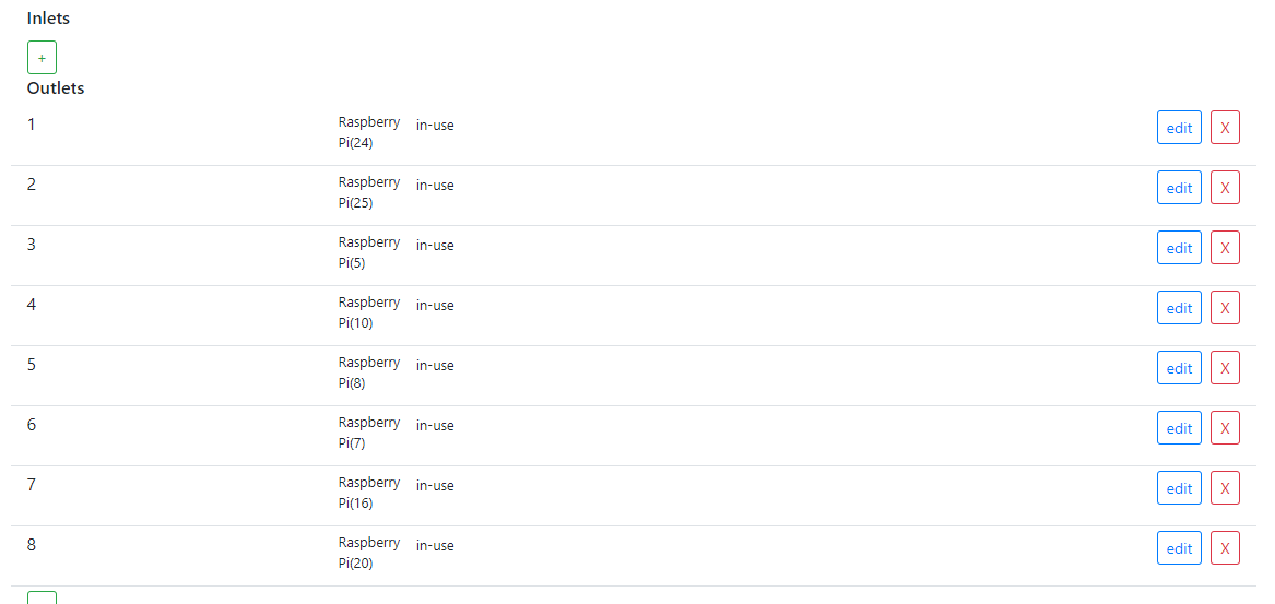
Regardless of which is better/more correct, either would allow for each LED to be individually switched on/off via the 'equipment' page in Reef-Pi? (I'm not using an ADJ...these are status only)

#2 wont work, as the first LED switched on will present as a short to ground. When the outlet is switched “on”, it presents as a very low resistance path to ground.
 

robottaway

Community Member
View Badges
Joined
Feb 11, 2019
Messages
56
Reaction score
62
Location
Bakersfiled, CA
Rating - 0%
0   0   0
Joining the Reef-PI movement care of the Pico controller board. I have to give it to you guys this is some inspiring work and shows how much can be accomplished when various skill sets converge. Here is a shot of me completing install.

59ea68f1c083402fc9af413b6295c12e.jpg


Temp probe worked right from get go. I had been worried about soldering it up wrong.

ADJ bar has some issue [emoji36] Outlet 1, 6 and 8 do not switch. 1 is not even providing power lol. Opened the bar up and not seeing anything jump out, maybe I need to test the output of DB9? Any debug tips appreciated [emoji848]

Going to test out my Kessil later have 2x 160we tuna blue chained together.

Looking forward to pH in future release! Bang for the buck is out of this world.
 

Bigtrout

Valuable Member
View Badges
Joined
Dec 16, 2018
Messages
1,189
Reaction score
2,826
Rating - 0%
0   0   0
Joining the Reef-PI movement care of the Pico controller board. I have to give it to you guys this is some inspiring work and shows how much can be accomplished when various skill sets converge. Here is a shot of me completing install.

59ea68f1c083402fc9af413b6295c12e.jpg


Temp probe worked right from get go. I had been worried about soldering it up wrong.

ADJ bar has some issue [emoji36] Outlet 1, 6 and 8 do not switch. 1 is not even providing power lol. Opened the bar up and not seeing anything jump out, maybe I need to test the output of DB9? Any debug tips appreciated [emoji848]

Going to test out my Kessil later have 2x 160we tuna blue chained together.

Looking forward to pH in future release! Bang for the buck is out of this world.
First off welcome to reef2reef.

Check the db9 outputs first...remember that the outputs sink current not source it...then look at the adj, there have been a few reports of bad solder joints.

Start a build thread and there is alot of helpful members to chime in and get you going!
 

rushbattle

Valuable Member
View Badges
Joined
Oct 19, 2016
Messages
1,347
Reaction score
1,644
Location
Equality
Rating - 0%
0   0   0
Joining the Reef-PI movement care of the Pico controller board. I have to give it to you guys this is some inspiring work and shows how much can be accomplished when various skill sets converge. Here is a shot of me completing install.

59ea68f1c083402fc9af413b6295c12e.jpg


Temp probe worked right from get go. I had been worried about soldering it up wrong.

ADJ bar has some issue [emoji36] Outlet 1, 6 and 8 do not switch. 1 is not even providing power lol. Opened the bar up and not seeing anything jump out, maybe I need to test the output of DB9? Any debug tips appreciated [emoji848]

Going to test out my Kessil later have 2x 160we tuna blue chained together.

Looking forward to pH in future release! Bang for the buck is out of this world.
I had some bad solder joints in both of my DJ strips. Check it out pretty carefully, all but one bad joint had solder on it, just didn't wet. One they didn't even solder at all.
 
OP
OP
theatrus

theatrus

Valuable Member
View Badges
Joined
Mar 26, 2016
Messages
1,957
Reaction score
3,355
Location
Sacramento, CA area
Rating - 0%
0   0   0
Woohoo, @robottaway , glad to see you here :) . Welcome to reef2reef.
These adj powestrips have poor QC, we heard of several bad soldering issues. If it’s from amazon, return

Agree. I’ve had to fix several of mine. Not a huge fan.

I can type up a diagnostic runout tonight to get things debugged.
 

rushbattle

Valuable Member
View Badges
Joined
Oct 19, 2016
Messages
1,347
Reaction score
1,644
Location
Equality
Rating - 0%
0   0   0
Agree. I’ve had to fix several of mine. Not a huge fan.

I can type up a diagnostic runout tonight to get things debugged.
At this point it seems rare to get a good one. Overall I like it for cost effectiveness, but inspite of how ignorant I sound here I was an electrical diagnostician for a while, so it’s easy to troubleshoot and fix rather than build from scratch for me.

The runout for troubleshooting will be hugely helpful for folks for sure.
 
Last edited:

robottaway

Community Member
View Badges
Joined
Feb 11, 2019
Messages
56
Reaction score
62
Location
Bakersfiled, CA
Rating - 0%
0   0   0
Thanks for the warm welcome and context on these ADJ. Looks like the iron was not up to temp when they put this thing together. Good feeling soldering the outlets with trouble will fix it. That failing I have a digital multimeter on the way to check DB9.
 
OP
OP
theatrus

theatrus

Valuable Member
View Badges
Joined
Mar 26, 2016
Messages
1,957
Reaction score
3,355
Location
Sacramento, CA area
Rating - 0%
0   0   0
Hi
How would connection work when using your own relay modules.
Will the standard 12v relay module boards work as is or will any other components be required (excluding the db9 converter)

Planning on using these
https://www.robotics.org.za/relays/REL8-OPTO

Yup. Any 12V relay would be just fine. The FETs used max at about 3A, but the thermal fuse will cutout power to the whole board at that point. The relays in the ADJ are about 100-150mA.
 

L0stmykeys

Active Member
View Badges
Joined
Nov 12, 2018
Messages
141
Reaction score
103
Rating - 0%
0   0   0
Does the pico board support only 1 temp sensor or am i reading old material?
 
Last edited:

dmolavi

Well-Known Member
View Badges
Joined
Jan 3, 2015
Messages
509
Reaction score
644
Location
United States
Rating - 0%
0   0   0
Does the pico board support only 1 temp sensor or am i reading old material?

I'm running 2 on my board. I think @Ranjib said he's run up to 7 on his non-Pico build. I suppose theoretically you're limited by whatever 1-wire can support.
 

L0stmykeys

Active Member
View Badges
Joined
Nov 12, 2018
Messages
141
Reaction score
103
Rating - 0%
0   0   0
Well I've hooked up 2 and they are both reading as separate temp sensors with unique ids but when you grab 1 and hold it both both sensor graphs increase evenly...
 

hockeyhead019

Well-Known Member
View Badges
Joined
Aug 21, 2017
Messages
564
Reaction score
578
Location
Philadelphia
Rating - 0%
0   0   0
@theatrus EDIT: whoops, didn't realize the board was moving from HDMI to DB9 for power strip compliance.

So then, how can I get my hands on the rev D board to start testing?? I'm planning an overall tank update and would love to include this to get rid of my old digital acquatics unit.
 
Last edited:

Ranjib

7500 Club Member
View Badges
Joined
Apr 16, 2016
Messages
9,843
Reaction score
17,058
Location
Pleasant Hill, Concord
Rating - 0%
0   0   0
Well I've hooked up 2 and they are both reading as separate temp sensors with unique ids but when you grab 1 and hold it both both sensor graphs increase evenly...
Graphs are updated at 10 second interval on the ui, the actual temperature reading frequency will be determined by what value you have specified in the temperature controller’s check frequency.
 

L0stmykeys

Active Member
View Badges
Joined
Nov 12, 2018
Messages
141
Reaction score
103
Rating - 0%
0   0   0
ive changed the frequency of both the sensors i think but i will see if i messed that up. usually the time i get to work on the controller is late in the evenings!
 
OP
OP
theatrus

theatrus

Valuable Member
View Badges
Joined
Mar 26, 2016
Messages
1,957
Reaction score
3,355
Location
Sacramento, CA area
Rating - 0%
0   0   0
@theatrus EDIT: whoops, didn't realize the board was moving from HDMI to DB9 for power strip compliance.

So then, how can I get my hands on the rev D board to start testing?? I'm planning an overall tank update and would love to include this to get rid of my old digital acquatics unit.

Give me a ping - I have more boards coming up, from a small shortage of TRS connectors :)
 
OP
OP
theatrus

theatrus

Valuable Member
View Badges
Joined
Mar 26, 2016
Messages
1,957
Reaction score
3,355
Location
Sacramento, CA area
Rating - 0%
0   0   0
A quick guide on checking if the DB9 connector is working as expected, to pinpoint an issue with the ADJ strip or the Pico board. Sorry this is late, its been a crazy week.

You will need:

- Pico board w/ Raspberry Pi
- A digital multimeter (any kind). I'm using a Fluke 87V in the pictures, but any $5 model will work.
- Two pieces of wire to poke into the DB9 port.

First, setup the ReefPi outlets to allow controlling all ports:

outlets.png


Next, configure in the Equipment tab one equipment per outlet (to let you toggle it easily)

connectors.png


Set the multi-meter to Volts DC. If its not an auto ranging meter, use the 20V range.

Next, connect one wire to pin 5 of the DB9. If you look at it head on, its the top left. There is labeling embossed in the black plastic to help locate it as well. You will want to connect this to the positive/red wire of the multimeter.

Next, connect to pin 1 (top right) using another wire to the other multimeter lead (black, V-, ground). It should look like this:

image1.jpeg


With the equipment toggle in the off position, you should see the multi-meter read approximately 0.5 volts. The exact value will differ a bit with variance, temperature, and meter accuracy, and isn't particularly important as long as its not 12V.

Toggle the equipment toggle in the Reef-Pi UI, and you should see the multi-meter jump to 12V:

image2.jpeg


As you toggle the UI, you should see the two voltages change back and forth.

Repeat this for every other pin by moving the black lead (you started in 1) through pins 2, 3, 4, 6, 7, 8, 9.

If you see something anomalous or you get a weird reading, let me know. If you can provide a picture of the section of the Pico board directly above the DB9 connector (the array of black squares) it will double confirm any defects that snuck out.

If everything is going great, the ADJ strip is most likely defunct. You can swap it out, or attempt a repair.
 

Creating a strong bulwark: Did you consider floor support for your reef tank?

  • I put a major focus on floor support.

    Votes: 65 39.4%
  • I put minimal focus on floor support.

    Votes: 36 21.8%
  • I put no focus on floor support.

    Votes: 58 35.2%
  • Other.

    Votes: 6 3.6%
Back
Top