

So, I got a Red Sea Reefer 525 this past Christmas and my obsession with perfecting my plumbing has not ended. I've hard plumbed everything in addition to building a manifold. I thought I would share my successes and failures.
First, I'll show you the state of things prior to adding reactors and fuge lights:
I had some simple goals with this setup:
First, I'll show you the state of things prior to adding reactors and fuge lights:
I had some simple goals with this setup:
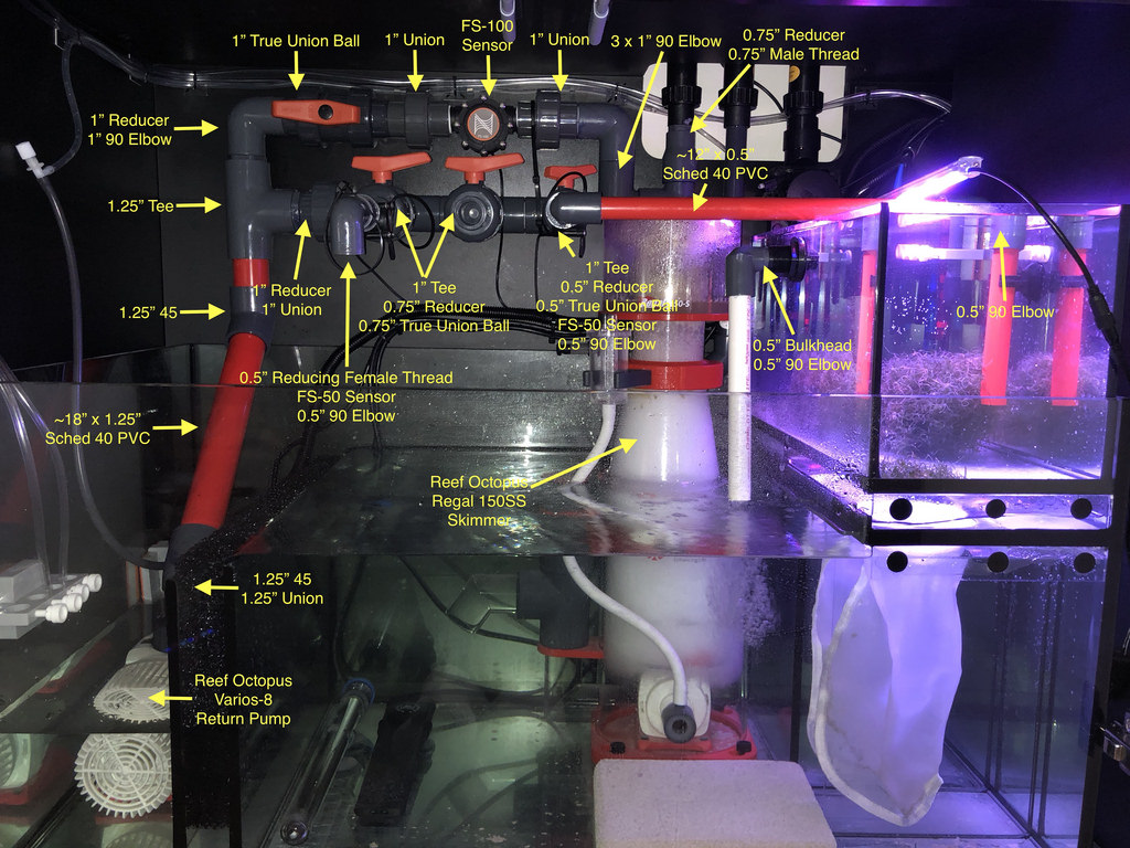
- convert the ~5gal ATO into a chaeto fuge
- run a single return pump
- Apex flow sensors on everything
- at least three manifold ports (carbon, gfo, and biopellet)
- display is getting about 500ghp through the FS-100 flow sensor
- i need to get install some support to hold the manifold in place (i'm reading having to drill anything into my cab through)
- i was only able to squeeze 3 manifold ports into this design instead of my desired 4. more on this to come in a future post
- fuge downpipe was super loud and flow was horrible with the way its pictured above. the pipe needed to be underwater and a gate valve installed to maintain siphon
- i have absolutely no tumble of my chaeto in the fuge
- dosing tubes on the left held-in by a Neptune magnet are flooded when the return goes off causing calcium and alk mix to run back into the line -- nasty!!
- headloss to the Varios-8 (2700GPH) seems to be major with 500gph to the display, 200gph to biopellets, 50gph and 50gph to the fuge.
- get one more manifold port after splitting my carbon and gfo into different reactors
- reduce friction so I can cycle more water to/from the display