DIY 3D printed Digital Color Analysis for Aquarium test tubes under $15 and no soldering required.

wacky123

Community Member
View Badges
Joined
Feb 24, 2021
Messages
27
Reaction score
23
Location
ottawa
Rating - 0%
0   0   0
I'm been working on this for while and i feel that it looks good enough to show.... i hope it helps others analysis digital color representation for people who are color blind like me, parts are pretty cheap possibly under $15 and no soldering required.

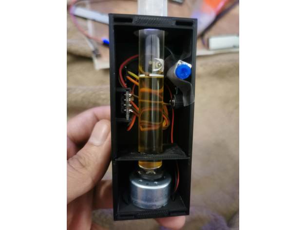
DIY Digital 3D Color Analysis for Aquarium test tubes, this device can be used to check color in the test tube with the digital color representation, in this case i will be using Api test kits

Note: newer model doesn't not require a resistor for led

Maker Video V:
https://tinyurl.com/397x5vjd

Maker 3D model:

dp.PNG IMG_20210216_211354.jpg IMG_20210216_211508.jpg IMG_20210217_130002.jpg pin_layout2.JPG
 

jsker

Reefing is all about the adventure
View Badges
Joined
Apr 11, 2015
Messages
24,974
Reaction score
79,737
Location
Saint Louis
Rating - 0%
0   0   0
Interesting, and cool at the same-time.
 
OP
OP
W

wacky123

Community Member
View Badges
Joined
Feb 24, 2021
Messages
27
Reaction score
23
Location
ottawa
Rating - 0%
0   0   0
Curious, why go with that color sensor instead of the TCS34725?
hmm that looks like very promising sensor, some how missed my list ... in my original analysis, i wanted a high res senor without led, since i want to pass light through the liquid and with variable light intensity since some of the solutions are ticker/cloudier than others, at the time this ISL29125 sensor seems like the right choice.
i'm suse as the time goes sensor will become strong and accurate
 
Last edited:

garbled

Well-Known Member
View Badges
Joined
Nov 10, 2018
Messages
772
Reaction score
1,045
Rating - 0%
0   0   0
It does have a pin to flip the LED off, if that's needed... I'm using it for another project, and so far I'm reasonably happy with it.
 
OP
OP
W

wacky123

Community Member
View Badges
Joined
Feb 24, 2021
Messages
27
Reaction score
23
Location
ottawa
Rating - 0%
0   0   0
Since this post i have update the schema to V2.
-no longer requires a tripod resistor and no need to calibration manually
-sensor and led on 3d models are moved down so there is no interference from the API sticker
-vial holes are made smaller so there is less friction while mixing.
-software is updated with multiple options of test kits
-made the 3d box smaller to shorter vile can fit in

future:
-would like build a community so others cans add there sample data chart for other test kits
-smart and accurate test algorithm so represented readings like 3.51ppm Nitrate

Note: V2 - 3D model has not been printed or test yet, so please let me know if there are issues.
 

laverda

2500 Club Member
View Badges
Joined
Jun 6, 2008
Messages
2,893
Reaction score
2,165
Location
Anaheim
Rating - 0%
0   0   0
you can buy ISL29125 from any where, might even find locally .... or if your feeling adventurous try a different sensor :)
That's easy for you to say. My knowledge of electronics is not that deep. I know nothing about the sensors, so would not know how to pick a different one. I did not know the number was a number other vendors would carry.
Nice build! It does seem a waste to design it around API test kits. I would like to build one for the Salifert kits I use. I just don't have any programing experience.
 

MikeTheNewbie

Active Member
View Badges
Joined
Aug 16, 2020
Messages
361
Reaction score
246
Location
Michigan
Rating - 0%
0   0   0
Hi @wacky123 I finally received my components and I'll start playing with them this week.
In the meantime, I looked at the code and wondered where did the RGB color ranges come from?
unsigned int redlow = 589;
unsigned int redhigh = 3870;
unsigned int greenlow = 961;
unsigned int greenhigh = 5181;
unsigned int bluelow = 773;
unsigned int bluehigh = 4109;
 
OP
OP
W

wacky123

Community Member
View Badges
Joined
Feb 24, 2021
Messages
27
Reaction score
23
Location
ottawa
Rating - 0%
0   0   0
Hi @wacky123 I finally received my components and I'll start playing with them this week.
In the meantime, I looked at the code and wondered where did the RGB color ranges come from?
unsigned int redlow = 589;
unsigned int redhigh = 3870;
unsigned int greenlow = 961;
unsigned int greenhigh = 5181;
unsigned int bluelow = 773;
unsigned int bluehigh = 4109;
That range of values for each color needs to be calibrated, i followed instruction here to calibrate the color range and used almost the same values. in the end you want 255 255 255 colors for clear water.
 

MikeTheNewbie

Active Member
View Badges
Joined
Aug 16, 2020
Messages
361
Reaction score
246
Location
Michigan
Rating - 0%
0   0   0
Great, thanks for the clarification.
What do you think about loading those calibration settings from the JSON file instead of hardcoding them? In case people end up with slightly different values due to differences in components.
I have Hanna checkers for Alkalinity, Nitrate, Phosphate and Copper but I really like your project. I'm specially interested in using it with RedSea or Nyos Nitrate and as the Hanna is a pain to use.
After building it I'd really like to use one of those ESP32s that have an OLED screen to see if I can setup and display the values without needing my phone. I saw one that has an integrated OLED and 18650 battery. Maybe it can work standalone? Lots of possibilities! I wish I had more time to play with this.
 

MikeTheNewbie

Active Member
View Badges
Joined
Aug 16, 2020
Messages
361
Reaction score
246
Location
Michigan
Rating - 0%
0   0   0
Hi @wacky123 @garbled, I recall from previous projects that were concerns about connecting DC motors / fans directly to the IO pins of microcontrollers or development boards. I think it was related to inductive charge (I'm not an electrical engineer but I do like electronics a lot).
Do you know if it is OK to connect these little motors to the ESP8266 without an intermediate DC motor driver?
 

garbled

Well-Known Member
View Badges
Joined
Nov 10, 2018
Messages
772
Reaction score
1,045
Rating - 0%
0   0   0
Don't connect a motor load directly to an ESP or arduino output, you will almost certainly fry the little thing. I don't remember where, but you can lookup the mA load max on the device, and it's really small. Much smaller than just about any motor you will find.

You need some kind of motor controller, or relay, or transistor, hooked up to a secondary power source to feed the motor, and use the ESP to switch it on. There are tons of diagrams on the web on how to do this, especially for simple on/off.
 

MikeTheNewbie

Active Member
View Badges
Joined
Aug 16, 2020
Messages
361
Reaction score
246
Location
Michigan
Rating - 0%
0   0   0
Thanks for the feedback. I found a cool "Wemos ESP-8266 Board with 0.96" OLED and Battery" and thought about using that to make this project standalone battery powered using the little screen to show the test results but then I noticed the motor was being driven from the board in the OP schematic. I guess I'll try to find a tiny dc motor driver I can power from that same battery or maybe stir externally in the meantime. I like the idea of stirring the couvette within the same device though. Maybe adding a little timer too.
Let's see how this thing develops.
@monkeyCmonkeyDo I didn't quite get your last comment.
 

Creating a strong bulwark: Did you consider floor support for your reef tank?

  • I put a major focus on floor support.

    Votes: 53 40.2%
  • I put minimal focus on floor support.

    Votes: 27 20.5%
  • I put no focus on floor support.

    Votes: 48 36.4%
  • Other.

    Votes: 4 3.0%
Back
Top