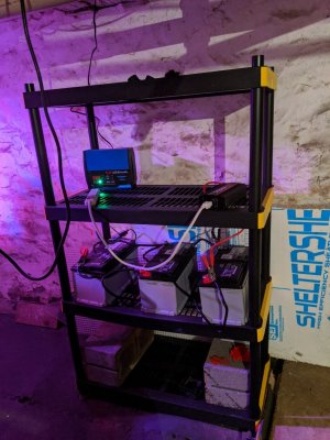
DIY battery backup

Ratherbeflyen

Well-Known Member
View Badges
Joined
Mar 9, 2018
Messages
571
Reaction score
935
Location
Houston
Rating - 0%
0   0   0
I made my own battery backup. It uses a 110v power relay to automatically switch between wall power and the battery backup. I used a couple of 7 amp hour batteries sealed lead acid batteries. My icecap 3k gyre pump comes with a 24v DC power supply, so I was going to run two 12v batteries in series, but it turns out the pump runs just fine on 12 volts. So I run the batteries in parallel (+ to + and - to -) to keep 12v and just add amp hours. I then added a 12v battery maintainer to keep the batteries fully charged.

I made a video how I put I put it together with (unpaid) links to the items used in the description.

 
OP
OP
Ratherbeflyen

Ratherbeflyen

Well-Known Member
View Badges
Joined
Mar 9, 2018
Messages
571
Reaction score
935
Location
Houston
Rating - 0%
0   0   0
If you can strip wire and clamp on wire connectors, you should be able to build one. I didn't have one in the video, but I did put in an inline fuse in on the positive battery cable for the final install. 12v dc power, especially with a fuse is lower risk electricity than anything higher voltage.
 

Thetankdoctor

Active Member
View Badges
Joined
Apr 20, 2020
Messages
385
Reaction score
541
Location
Ohio
Rating - 0%
0   0   0
I use an old computer battery back up unit. I just open it up throw away the battery and add wire and clips and use a deep cycle boat battery hooked up to the backup unit I can keep my dc return punp and skimmer going for about 8-10 hours. When the power goes out it automatically comes on. Also you can get the unit really cheap at like good will or something as people get rid of them when the batteries go bad...
 

Biglew11

Valuable Member
View Badges
Joined
May 10, 2020
Messages
1,577
Reaction score
1,882
Location
New York
Rating - 0%
0   0   0
I use an old computer battery back up unit. I just open it up throw away the battery and add wire and clips and use a deep cycle boat battery hooked up to the backup unit I can keep my dc return punp and skimmer going for about 8-10 hours. When the power goes out it automatically comes on. Also you can get the unit really cheap at like good will or something as people get rid of them when the batteries go bad...

I did the same thing using two 600 A.H. batteries. Apex programed to run only the essentials.
 
OP
OP
Ratherbeflyen

Ratherbeflyen

Well-Known Member
View Badges
Joined
Mar 9, 2018
Messages
571
Reaction score
935
Location
Houston
Rating - 0%
0   0   0
How long does the OP run the gyre for?

That's a good question and I initially didn't know, but it was a test I needed to do.

The batteries I used are 7 AH sealed lead acid batteries. Completely discharging lead acid batteries can damage them and shorten their life. Its best if you don't discharge the batteries past 50%. Based on the chart below, 12.2 volts is about a 50% state of charge. So I decided to run the test until the batteries reached 50% state of charge. If the power was actually out, I would be happy to run the batteries into the ground and buy new ones if it meant saving my reef. For a test, I would rather not risk damaging the batteries.
1590721767321.png


For the test, I unplugged the outlets so it would switch over the battery backup just like in a power failure. The batteries started the test at 12.8 volts. Two days later (51 1/2 hours) running continuously on the battery backup, the batteries showed 12.2 volts where I stopped the test. Extrapolating out the remaining 50% battery life, the pump would run for ~103 hours or just over 4 days.

I knew that running one DC pump directly off of DC batteries would produce very long run times. The uninterrupted AC power supplies or computer backups will never get anywhere near the run times with the same pump, even with a bigger battery. That is because they have a power inverter that changes the DC battery power into AC power. Then the pumps power supply converts it back into DC power to run the pump. These conversion steps waste energy and reduce the amount of power available to run the pump. For me, it makes no sense to spend more money on an uninterruptible power supply (UPS) that runs the wave maker for less time. That's why I chose to build my battery backup this way, and would do it the same way again.

If I was going to make a change, my return pump is also 24v DC and will run on a single 12 volt battery. However, at about 5 times more amperage draw. So my current batteries would run the return pump for 1/5 the time or about 20 hours. A size 27 65 amp hour AGM battery is available at Costco for $88 and would run my return pump for ~4 days again. Running the return pump would keep the sump from being stagnant as well as provide superior surface skimmer, filtration, and oxygenation. I'm not seriously entertaining make this change though. The only reason is it's very unlikely my tank will ever go 4 days with no power. If the power goes out, and I know about it, I get out a small generator that runs my tank, fridge, freezer and window air conditioner. Even if we go out of town for a few days, I have a neighbor come over and feed my fish once a day and check on the tank. So I estimate that ~30 hours of battery backup is probably the longest I would need. However, for LESS money, the much longer run time is a good piece of mind. It's also more reliable having less converters and inverters that may fail.
 

Metcho

Active Member
View Badges
Joined
Jul 17, 2017
Messages
424
Reaction score
325
Rating - 0%
0   0   0
That's a good question and I initially didn't know, but it was a test I needed to do.

The batteries I used are 7 AH sealed lead acid batteries. Completely discharging lead acid batteries can damage them and shorten their life. Its best if you don't discharge the batteries past 50%. Based on the chart below, 12.2 volts is about a 50% state of charge. So I decided to run the test until the batteries reached 50% state of charge. If the power was actually out, I would be happy to run the batteries into the ground and buy new ones if it meant saving my reef. For a test, I would rather not risk damaging the batteries. Could you please help me to understand what wire go where on relay.
Thanks
1590721767321.png


For the test, I unplugged the outlets so it would switch over the battery backup just like in a power failure. The batteries started the test at 12.8 volts. Two days later (51 1/2 hours) running continuously on the battery backup, the batteries showed 12.2 volts where I stopped the test. Extrapolating out the remaining 50% battery life, the pump would run for ~103 hours or just over 4 days.

I knew that running one DC pump directly off of DC batteries would produce very long run times. The uninterrupted AC power supplies or computer backups will never get anywhere near the run times with the same pump, even with a bigger battery. That is because they have a power inverter that changes the DC battery power into AC power. Then the pumps power supply converts it back into DC power to run the pump. These conversion steps waste energy and reduce the amount of power available to run the pump. For me, it makes no sense to spend more money on an uninterruptible power supply (UPS) that runs the wave maker for less time. That's why I chose to build my battery backup this way, and would do it the same way again.

If I was going to make a change, my return pump is also 24v DC and will run on a single 12 volt battery. However, at about 5 times more amperage draw. So my current batteries would run the return pump for 1/5 the time or about 20 hours. A size 27 65 amp hour AGM battery is available at Costco for $88 and would run my return pump for ~4 days again. Running the return pump would keep the sump from being stagnant as well as provide superior surface skimmer, filtration, and oxygenation. I'm not seriously entertaining make this change though. The only reason is it's very unlikely my tank will ever go 4 days with no power. If the power goes out, and I know about it, I get out a small generator that runs my tank, fridge, freezer and window air conditioner. Even if we go out of town for a few days, I have a neighbor come over and feed my fish once a day and check on the tank. So I estimate that ~30 hours of battery backup is probably the longest I would need. However, for LESS money, the much longer run time is a good piece of mind. It's also more reliable having less converters and inverters that may fail.
I’ve got a question I watched the video but not quite following the order the wires were completely hooked up on the relay. I’m wiring up a 24vdc relay DPDT two 12v making 24v and the controller and power from wall that’s ac to dc plug. Was trying to figure out how what wires went where on relay.
E5CD858E-0E41-4455-8729-508A6E156416.jpeg
 

Pistondog

5000 Club Member
View Badges
Joined
Jun 28, 2020
Messages
5,307
Reaction score
9,443
Rating - 0%
0   0   0
I’ve got a question I watched the video but not quite following the order the wires were completely hooked up on the relay. I’m wiring up a 24vdc relay DPDT two 12v making 24v and the controller and power from wall that’s ac to dc plug. Was trying to figure out how what wires went where on relay.
E5CD858E-0E41-4455-8729-508A6E156416.jpeg
I think you represented the spades on the relay. There is a receiver socket with screw terminals you usually wire to that the relay plugs into.
Sometimes the side of the relay has a schematic of the relays pinouts.
The 2 lower vertical pins are usually the coil, the other 2 columns are the related sets of contacts. 1 is a common and switches between the other 2 when the relay is energized.
Relays come in different coil voltages like 120 vac or 24vdc and others. If you mix them up, apply 120 to 24v coil, you will let out the magic blue smoke that makes them work.
If your relay is labeled, Google it for more info.
 

Metcho

Active Member
View Badges
Joined
Jul 17, 2017
Messages
424
Reaction score
325
Rating - 0%
0   0   0
Yeah I googled it and couldn’t find the answer. I know the battery goes to the NC and power from AC to DC plug goes to NO but not sure about the coil and common I think the controller goes to common
 

Pistondog

5000 Club Member
View Badges
Joined
Jun 28, 2020
Messages
5,307
Reaction score
9,443
Rating - 0%
0   0   0
Yeah I googled it and couldn’t find the answer. I know the battery goes to the NC and power from AC to DC plug goes to NO but not sure about the coil and common I think the controller goes to common
The coil should get the 120ac so when its on, the relay is energized and the controller gets ac to dc power on fhe n.o. contact. When the 120 is off, the n.c battery supplies power to the controller via common.
Sounds like you have it.
Just make sure coil voltage is 120vac.
 
OP
OP
Ratherbeflyen

Ratherbeflyen

Well-Known Member
View Badges
Joined
Mar 9, 2018
Messages
571
Reaction score
935
Location
Houston
Rating - 0%
0   0   0
The relay I used, and the screen shot from the video is as follows.

Capture.PNG


There are many different relays though, so yours may not be the same. It doesn't really matter, the working principal is the same.

The 110v is what charges the electromagnet. When you're correctly plugged into that terminal, you'll hear a click when power is added or removed. That click is the electromagnet pulling or releasing the contact switch/paddle. None of the other connectors will make that click.

Out of the remaining terminals, one pair is connected the back of the paddle/switch. (It's the white wire in the photo.) That is the terminal to run to the pump. The other two pairs of connectors will complete the circuit to the paddle, white wire, pump, etc either when the 110v is on, or off. When the 110v is on, use the connector that completes the circuit to the power supply. When the 110v is off, use the last remaining connector to go to the battery bank.
 

Metcho

Active Member
View Badges
Joined
Jul 17, 2017
Messages
424
Reaction score
325
Rating - 0%
0   0   0
The relay I used, and the screen shot from the video is as follows.

Capture.PNG


There are many different relays though, so yours may not be the same. It doesn't really matter, the working principal is the same.

The 110v is what charges the electromagnet. When you're correctly plugged into that terminal, you'll hear a click when power is added or removed. That click is the electromagnet pulling or releasing the contact switch/paddle. None of the other connectors will make that click.

Out of the remaining terminals, one pair is connected the back of the paddle/switch. (It's the white wire in the photo.) That is the terminal to run to the pump. The other two pairs of connectors will complete the circuit to the paddle, white wire, pump, etc either when the 110v is on, or off. When the 110v is on, use the connector that completes the circuit to the power supply. When the 110v is off, use the last remaining connector to go to the battery bank.
Okay thanks for the photo and explanation
 

Nurse.Reef.Reapeat

Well-Known Member
View Badges
Joined
Sep 3, 2017
Messages
600
Reaction score
346
Location
New Jersey
Rating - 0%
0   0   0
I made my own battery backup. It uses a 110v power relay to automatically switch between wall power and the battery backup. I used a couple of 7 amp hour batteries sealed lead acid batteries. My icecap 3k gyre pump comes with a 24v DC power supply, so I was going to run two 12v batteries in series, but it turns out the pump runs just fine on 12 volts. So I run the batteries in parallel (+ to + and - to -) to keep 12v and just add amp hours. I then added a 12v battery maintainer to keep the batteries fully charged.

I made a video how I put I put it together with (unpaid) links to the items used in the description.


Im so glad i found your video and this post. I am trying to built one for my for my Nuvo 10 return pumps which are Mighty Jets. it draws 15 watts each and uses 24V. I hope you can help me find the best ah for the battery. I might not need it to run 2 days but at least 24 hours. and also a Diagram would be much appreciated.
 
Last edited:
OP
OP
Ratherbeflyen

Ratherbeflyen

Well-Known Member
View Badges
Joined
Mar 9, 2018
Messages
571
Reaction score
935
Location
Houston
Rating - 0%
0   0   0
Im so glad i found your video and this post. I am trying to built one for my for my Nuvo 10 return pumps which are Mighty Jets. it draws 15 watts each and uses 24V. I hope you can help me find the best ah for the battery. I might not need it to run 2 days but at least 24 hours. and also a Diagram would be much appreciated.

You can convert electrical energy to amps (watts / volts = amps). For your mighty jet, 15 watts / 24 volts = 0.625 amps. So your pumps will run for 1 hour for each 0.625 amp hour of battery. If you bought a pair of 7 amp hour batteries like I did, one pump would run continuously for ~ 22 hours. A couple of caveats, the first is lead acid batteries are usually closer to 13 - 13.5 volts when fully charged. So you'll probably get more run time than 22 hours. The second caveat is if you use lead acid batteries, they will be damaged if you drain them by more than ~50% of the total battery capacity. I didn't make any effort to save the batteries because they are cheaper to replace than almost any single item in the tank. If I lost power for days, I at least know there will be some water oxygenation. Unless you're gone from your tank for several days at a time, a pair of 7 or 10 amp hour batteries should work just fine.


As for the wiring diagram, I could make one, but if you didn't have the same electrical relay it may be detrimental to you. A different brand or type of relay may have different connections than I used. If you get a relay, it may come with a wiring diagram. If you pick one up, post a picture of it here and I'll help you get it wired up.
 

Nurse.Reef.Reapeat

Well-Known Member
View Badges
Joined
Sep 3, 2017
Messages
600
Reaction score
346
Location
New Jersey
Rating - 0%
0   0   0
The relay I used, and the screen shot from the video is as follows.

Capture.PNG


There are many different relays though, so yours may not be the same. It doesn't really matter, the working principal is the same.

The 110v is what charges the electromagnet. When you're correctly plugged into that terminal, you'll hear a click when power is added or removed. That click is the electromagnet pulling or releasing the contact switch/paddle. None of the other connectors will make that click.

Out of the remaining terminals, one pair is connected the back of the paddle/switch. (It's the white wire in the photo.) That is the terminal to run to the pump. The other two pairs of connectors will complete the circuit to the paddle, white wire, pump, etc either when the 110v is on, or off. When the 110v is on, use the connector that completes the circuit to the power supply. When the 110v is off, use the last remaining connector to go to the battery bank.

clarification. Because we use the DC power Supply when electricity is working, what’s the use of the 110V? Is there a relay that I can use for switching between battery operation and DC power outlet operation?
 
Back
Top